
Load measuring transducer including elastic structure and gauge using induced voltage, and load measuring system using the same

a technology of load measurement transducer and elastic structure, which is applied in the direction of force measurement, force measurement, instruments, etc., can solve the problems of non-uniform mechanical properties that cannot be easily predicted, the difficulty of implementing a load cell with a higher accuracy, and the disturbance of the extension and compression behavior of the structur

Inactive Publication Date: 2007-08-21
PARK HUENG JOON
View PDF15 Cites 2 Cited by
  • Summary
  • Abstract
  • Description
  • Claims
  • Application Information

AI Technical Summary

Benefits of technology

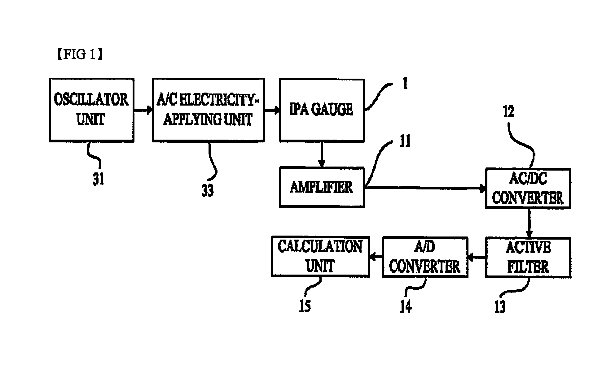
[0009]Accordingly, the present invention is conceived to solve the problems in the conventional load measuring transducer and system. An object of the present invention is to provide a load measuring transducer and system, which are more simplified in their structures and components and can measure load with higher accuracy.
[0010]Another object of the present invention is to provide a load measuring transducer and system, which include a gauge capable of correctly measuring load even when the load is eccentrically applied.
[0017]According to this load measuring transducer, since the first and second portions in the gauge pattern are concentric with each other, the load measuring transducer can correctly measure load even when the load is applied to the structure in a slightly eccentric manner.
[0025]According to this load measuring transducer, since the moving gauge moves in a direction perpendicular to the longitudinal direction of the gauge, the load can be measured without limitations on the moving distance of the moving gauge as compared to the previous load measuring transducer including the moving gauge which moves in the longitudinal direction of the gauge.

Problems solved by technology

It is very difficult to implement a load cell with accuracy higher than the above accuracy.
This is because there are problems in that a layer of an adhesive used to attach a strain gauge to a structure distorts and transfers a strain produced in the structure and also disturbs extension and compression behaviors of the structure.
Further, since the adhesive is made of polymer and has an inhomogeneous amorphous structure, it has non-uniform mechanical properties that cannot be easily predicted.
Inherent features of a strain gauge itself also adversely affect the implementation of higher accuracy.
This is because there is a problem in that a back plate which is made of polymer such as phenol or polyamide and placed below a resistive material of the strain gauge inhibits the transfer of a strain without distortion in the same manner as the layer of the adhesive.
Further, since it is difficult to achieve a uniform profile of the resistive material throughout the strain gauge, it is also difficult to obtain uniform deformation thereof proportional to a compressive or tensile strain of a structure.
However, since this load measuring transducer employs a very complicated mechanical mechanism, the load measuring transducer is difficult to manufacture and is very expensive.
In addition, there are electrical and spatial limitations on increase of electromagnetic force serving as balancing force for applied load.
Further, since the complicated mechanical mechanism includes a lot of thin hinges, there are problems in that it is not suitable for measurement of heavy load and it is very vulnerable to external impact.
Due to the above difficulties or problems, such a load measuring transducer cannot be easily used in general-purpose commercial electronic scales or industrial electronic scales and also be restrictively used only in special-purpose electronic scales.

Method used


Image

  • Load measuring transducer including elastic structure and gauge using induced voltage, and load measuring system using the same
  • Load measuring transducer including elastic structure and gauge using induced voltage, and load measuring system using the same
  • Load measuring transducer including elastic structure and gauge using induced voltage, and load measuring system using the same

Examples


Embodiment Construction

[0009]Accordingly, the present invention is conceived to solve the problems in the conventional load measuring transducer and system. An object of the present invention is to provide a load measuring transducer and system, which are more simplified in their structures and components and can measure load with higher accuracy.

[0010]Another object of the present invention is to provide a load measuring transducer and system, which include a gauge capable of correctly measuring load even when the load is eccentrically applied.

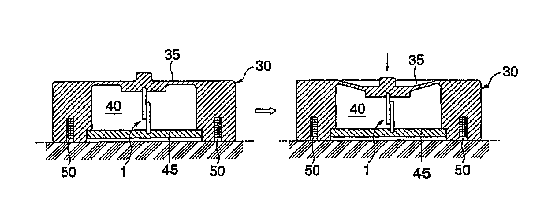
[0011]The load measuring transducer for achieving the above purpose of the present invention comprises a stationary gauge which is constructed of a plurality of repeated electric wire patterns with a predetermined pitch and has both ends to which AC electricity is applied; and a moving gauge which is provided to move in a longitudinal direction of the stationary gauge without contacting with the stationary gauge in response to the occurrence of the elastic deformat...


PUM

PropertyMeasurementUnit
elastic deformationaaaaaaaaaa
induced voltageaaaaaaaaaa
shapeaaaaaaaaaa

Abstract

The present invention relates to a load measuring transducer including gauges and elastic structure and weighing system for measuring weight applied to a structure. The load measuring transducer of the present invention comprises a stationary gauge which is constructed of a plurality of repeated coil (or electric wire) patterns with a predetermined pitch and has both ends to which an AC electricity is applied; and a moving gauge which is provided to move in a longitudinal direction (or perpendicular direction with respect to the longitudinal direction) of the stationary gauge without contact therewith in response to the occurrence of the elastic deformation of the deformation-producing portion of the structure of the transducer.

Description

FIELD OF THE INVENTION[0001]The present invention relates to a load measuring transducer including an elastic structure and a gauge, and a load measuring system using the same. More particularly, the present invention relates to a load measuring transducer and system using the same, wherein load is applied to an elastically deformable structure to produce an elastic deformation in the structure and the applied load is then measured using a gauge in which an induced voltage is produced according to the produced elastic deformation.TECHNICAL BACKGROUND[0002]As a load measuring transducer generally employed in general-purpose electronic scales, industrial electronic scales and the like in the related art, there has been widely used a so-called “electric resistance type load cell” that employs a resistive wire constructing a strain gauge. In this load cell, when a strain is generated in a structure due to application of load to the structure, the strain is detected as a change in electr...

Claims


Application Information

Patent Timeline
Patent Type & Authority Patents(United States)
IPC IPC(8): G01L1/10G01G3/12G01G3/14G01G7/00
CPCG01G3/12G01G7/00G01G7/02G01L1/14G01D5/183
Inventor PARK, HUENG JOON
Owner PARK HUENG JOON
Learn More