Optical fiber connection tool and optical fiber connection method

a technology of optical fiber and connecting tool, which is applied in the direction of optics, instruments, optical light guides, etc., to achieve the effect of avoiding the increase of loss and preventing the connection of defects

Inactive Publication Date: 2007-08-21
FUJIKURA LTD
View PDF16 Cites 19 Cited by
  • Summary
  • Abstract
  • Description
  • Claims
  • Application Information

AI Technical Summary

Benefits of technology

[0008]The present invention was made in consideration of the above explained conventional problems. An object of the present invention is to provide an optical fiber connecting tool and a method for connecting optical fibers in which it is possible to release the deformation which is generated on the tip section of at least the optical fiber by the butt-connecting force between the optical fibers and prevent the defect connection while avoiding the increase in a loss which is cause by a bent optical fiber and a loss in the tip section of the optical fiber.
[0011]According to the optical fiber connecting tool according to the present invention, an open / close member is inserted in one clamping section so as to open the clamping section. Other open / close member is inserted in the another clamping section so as to open the another clamping section. In addition, the optical fiber is inserted in the connecting structure so as to butt-connect the optical fibers. In such a case, it is acceptable if the optical fiber may be inserted from both of facing sides of the connecting structure. Also, it is acceptable if there is a relationship such that either one of the optical fibers is a pre-installed optical fiber which is inserted in the connecting structure and the other one of optical fibers is a newly installed optical fiber which is butt-connected to the pre-installed optical fiber. In addition, either one of the open / close member is extracted from the clamping section and the clamping section is closed; thus the optical fibers are clamped under the butt-connected condition. In addition, after that, the other open / close member is extracted from the another clamping section, and the another clamping section is closed: thus, the optical fibers are clamped. By doing this, after closing the one clamping section, it is possible to maintain the connecting condition by steps for closing the another clamping section while there is few deformation in the optical fiber which is caused by the butt-connecting force which is applied to the optical fiber. That is, it is possible to release the deformation in a direction of the optical fiber before closing the other clamping section even if there is a deformation which is generated on the tip sections of the both of the optical fibers due to the butt-connecting force of the optical fibers. Therefore, the tips of the both of the optical fibers are not clamped under such a deformed condition. Also, the tip sections of the both of the optical fibers are not damaged due to the bent optical fibers and an increase in the loss. Therefore, it is possible to restrict the defect connection; thus, it is possible to enhance the reliability greatly.
[0012]Also, in the optical fiber connecting tool according to the present invention, it is possible to adapt a structure in which one of the optical fibers which are butt-connected by the connecting structure is a pre-installed optical fiber which is previously inserted in the clamping section from one of the connecting structure by fixing in a predetermined position in the connecting structure by an optical fiber fixing section, another one of the optical fiber which is butt-connected by the connecting structure is inserted in the clamping section via another clamping section from other side of the connecting structure so as to be a newly installed optical fiber which is butt-connected to the optical fiber in the clamping section, the another clamping section clamps a section which protrudes from the clamping section for the newly installed optical fiber which is clamped by the clamp. According to the optical fiber connecting tool according to the present invention, an open / close member is inserted in a clamping section so as to open the clamping section. Other open / close member is inserted in the other clamping section so as to open the other clamping section. The connecting structure performs a butt-connecting operation for the tip of the pre-installed optical fiber which is disposed in the connecting structure in advance to the tip of the newly installed optical fiber by inserting the newly installed optical fiber in the one clamping section via another clamping section. In addition, either one of the open / close member is extracted from the clamping section and the clamping section is closed; thus the pre-installed optical fiber and the newly-installed optical fiber are clamped under the butt-connected condition. In addition, after that, the other open / close member is extracted from the other clamping section, and the other clamping section is closed: thus, the newly installed optical fiber is clamped. By doing this, it is possible to connect the pre-installed optical fiber and the newly-installed optical fiber without generating deformation. Therefore, it is possible to release the deformation in a direction of the newly installed optical fiber before closing the other clamping section even if there is a deformation which is generated on the tip sections of the newly installed optical fiber against the pre-installed optical fiber due to the butt-connecting force of the optical fibers. Therefore, the tips of the both of the optical fibers are not clamped under such a deformed condition. Also, the tip sections of the both of the optical fibers are not damaged due to the bent optical fibers and an increase in the loss. Therefore, it is possible to restrict the defect connection; thus, it is possible to enhance the reliability greatly.

Problems solved by technology

However, in the above explained optical fiber connecting tool, in a case in which the tip section of both of the optical fibers is deformed by a butt-connecting force of the newly installed optical fiber against the pre-installed optical fiber near the optical fiber connector, both of the optical fibers are clamped under such a deformed condition; thus, there are problems such as an increase in a loss due to a bent optical fiber and a damage of the tip of the optical fiber which is caused by a concentrated stress to the tip section of the both of the deformed optical fibers; therefore, these problems may cause a defect connection.

Method used


Image

  • Optical fiber connection tool and optical fiber connection method
  • Optical fiber connection tool and optical fiber connection method
  • Optical fiber connection tool and optical fiber connection method

Examples


Embodiment Construction

[0047]The present invention is explained in detail with reference to attached drawings.

[0048]Hereinafter, the embodiments of the present invention which are shown in the drawings are explained.

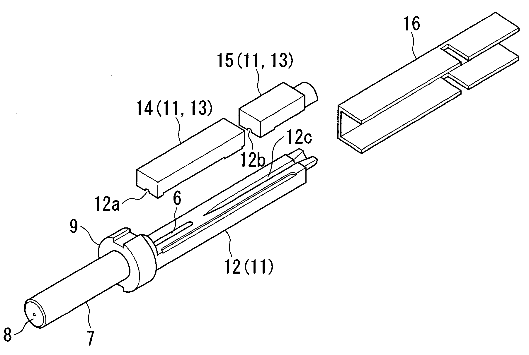
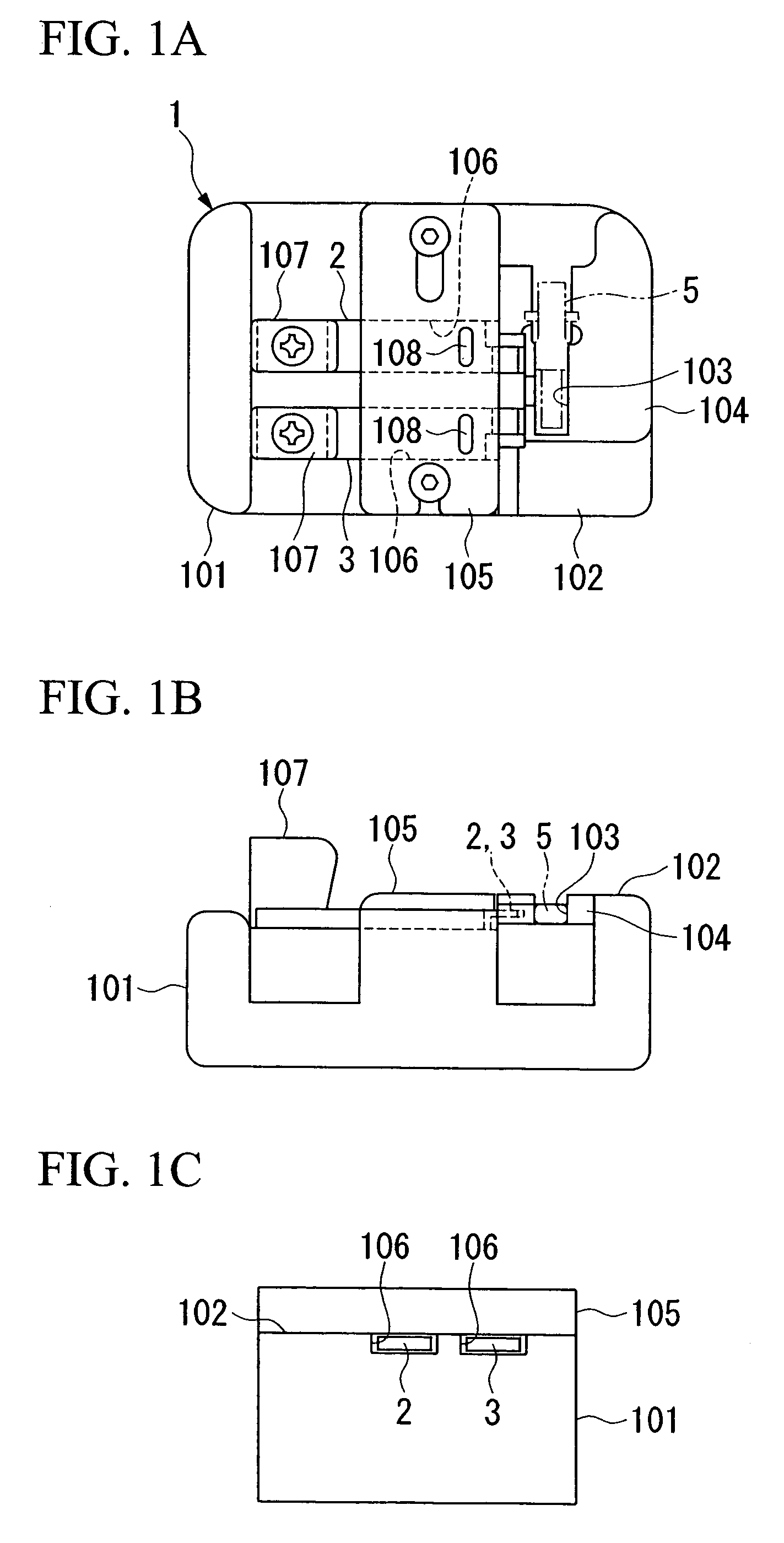
[0049]FIGS. 1 to 15 show a first embodiment of the optical fiber connecting tool according to the present invention. This optical fiber connecting tool 1 can be applied effectively for a case in which the optical fiber connecting part is attached to a tip section of the optical fiber. As shown in FIGS. 1A and B, the optical fiber connecting tool 1 is provided with a base 101 which fixes an optical fiber connecting part 5, and two open / clOse members 2, 3 which are disposed on the base 101.

[0050]The optical fiber connecting tool 1 according to the present invention can be applied for various type of optical fiber connecting tools 5.

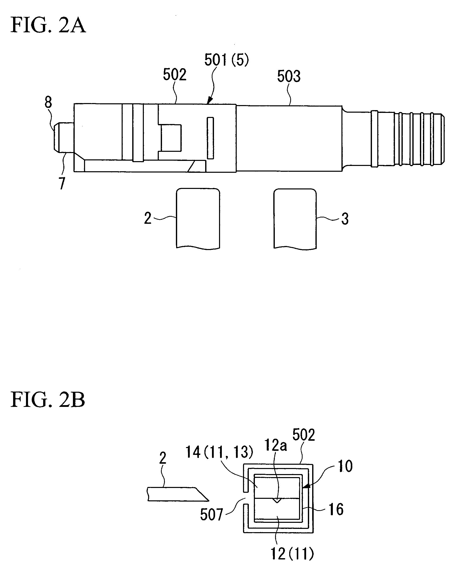
[0051]The optical fiber connecting part 5 which is shown in FIG. 2A to FIG. 4 contains a ferule 7 of an SC (SC; Single fiber coupling optical fiber connector) optical...


PUM


Abstract

An optical fiber connecting tool is provided in which an optical fiber connecting tool 5 is used which has a ferule 7, a connecting structure 10 which has two clamping sections 18, 19 which are disposed in a ferule 7. A pre-installed optical fiber 6 and a newly installed optical fiber 17 are clamped in a butt-connected condition by a clamping section 18. The newly installed optical fiber 17 is clamped by the other clamping section 19. An optical fiber connecting tool 1 is provided which has an open / close member 2 which is detachably disposed on the clamping section 18 and another open / close member 3 which is detachably disposed on the another clamping section 19 such that the both of the open / close members 2, 3 can be operated independently. Also, a method for connecting optical fibers according to the present invention prevents an increase in a loss due to a bent optical fiber and a damage in the optical fiber by extracting the open / close member 2 from the clamping section 18 before extracting the open / close member 3 from the another clamping section and dispose a deformation which is generated on the tip section of the optical fiber when the optical fiber connecting part is attached on the tip section of the optical fiber according to steps for performing an extracting operation for the open / close member e from the another clamping section. Here, for the optical fiber connecting part, for example, various members can be adapted such as a member which does not have the above explained ferule, and a member which realize a connection and a clamping operation for the optical fibers by a structure of only the above explained connecting structure.

Description

TECHNICAL FIELD [0001]The present invention relates to an optical fiber connecting tool and a method for connecting optical fibers. In particular, the present invention relates to an optical fiber connecting tools and a method for connecting optical fibers which are effective for connecting the pre-installed optical fiber and the newly installed optical fiber to the optical fiber connecting part by a connecting structure of the optical fiber connecting part.BACKGROUND ART [0002]Recent year, an optical fiber connector which is provided with a ferule in which an optical fiber is inserted in a center of the ferule and a connecting structure which is disposed in a tip section of the ferule is proposed for an optical fiber connector which can be attached to the tip section of the optical fiber easily.[0003]In such a case, the connecting structure is provided with a two-divided connecting elements which are formed by assembling two divided halves and a clamping spring which engages to the...

Claims


Application Information

Patent Timeline
Patent Type & Authority Patents(United States)
IPC IPC(8): G02B6/255G02B6/36G02B6/38
CPCG02B6/3636G02B6/3846G02B6/3652G02B6/3806G02B6/3898G02B6/36G02B6/24
Inventor SAITO, DAIGOTAKIZAWA, KAZUHIRO
Owner FUJIKURA LTD
Why Eureka
Try Eureka