Female connector

a female connector and connector technology, applied in the direction of dustproof/splashproof/drip-proof/waterproof/flameproof connection, coupling device connection, etc., can solve the problems of poor connection, inability to conduct electrically between the contactor and the plug blade, etc., to prevent poor connection

Active Publication Date: 2014-10-02
PANASONIC INTELLECTUAL PROPERTY MANAGEMENT CO LTD
View PDF4 Cites 5 Cited by
  • Summary
  • Abstract
  • Description
  • Claims
  • Application Information

AI Technical Summary

Benefits of technology

[0009]Hence, it is an object of the present invention to provide a female connector which can prevent poor connection.
[0010]A female connector of the present invention is installed at an end of a cable in which a plurality of electric wires are bundled, and includes: a plurality of contactors which are made of conductive material and connected to the plurality of electric wires, respectively; a holding body designed to hold the plurality of contactors; a body having a housing recess designed to house the plurality of contactors and the holding body; a holder formed in an annular shape in which the cable is inserted and designed to prevent the holding body from falling from the housing recess by coupling to the body; and a cover formed by double molding so as to cover the holder in a state where the cable is inserted into the holder and where the holder and the body are coupled to each other. The holder is designed to be in close contact with the cable along a whole circumference thereof.
[0012]According to the present invention, with having the holder being in close contact with the cable along the whole circumference thereof, it is possible to prevent resin which forms the cover, from flowing into a housing recess from a gap between the cable and the holder at the time of producing the cover in manufacturing the female connector. Thereby, it is possible to prevent poor connection caused by the resin.

Problems solved by technology

In the female connector as described above, if resin which forms the cover enters around a contactor from the gap between the holder and the cable at the time of producing the cover in manufacturing the female connector, there may cause a problem of poor connection such that the electrical conduction between the contactor and the plug blade is inhibited by the resin which covers the contactor.

Method used


Image

  • Female connector
  • Female connector
  • Female connector

Examples


Embodiment Construction

[0018]The best mode for carrying out the present invention will be explained below, with reference to the drawings.

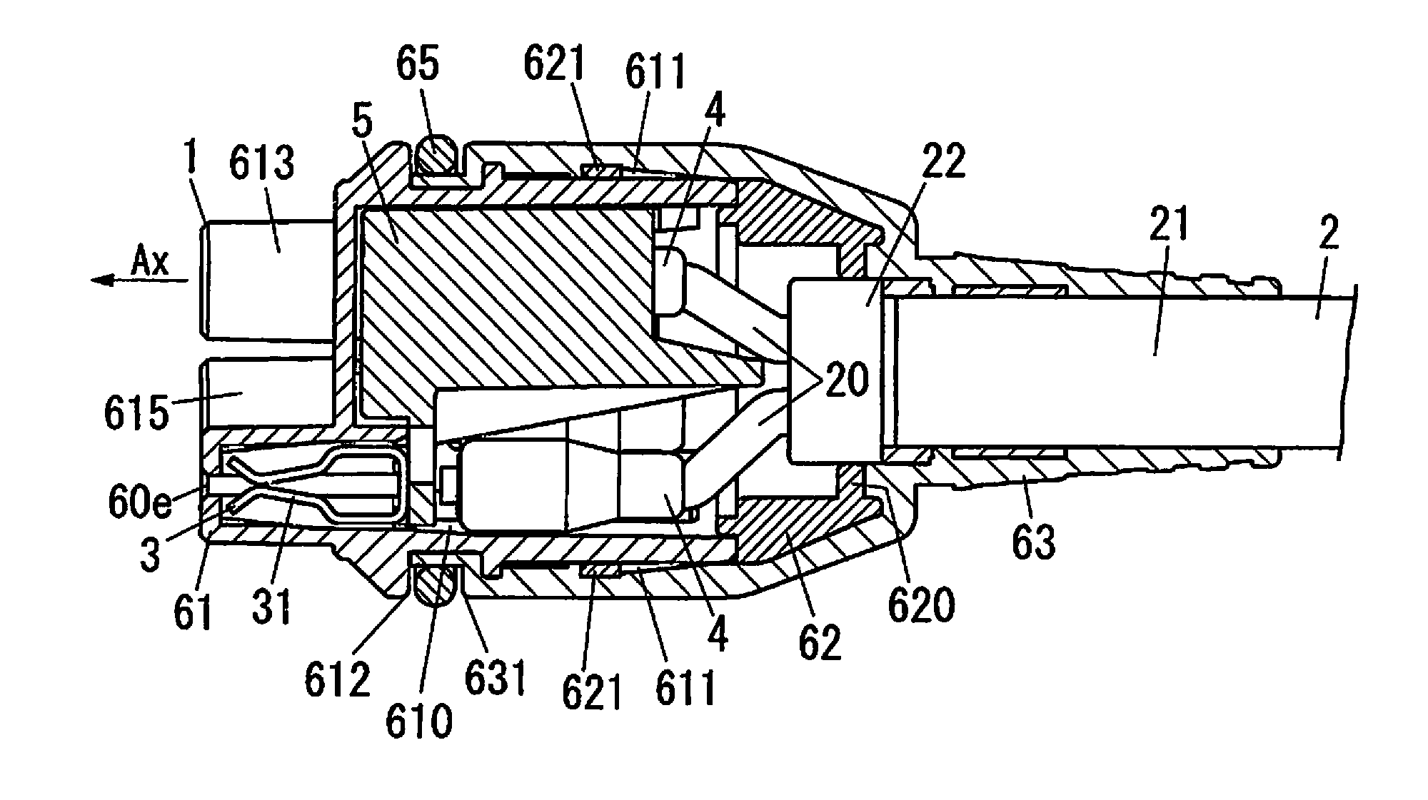
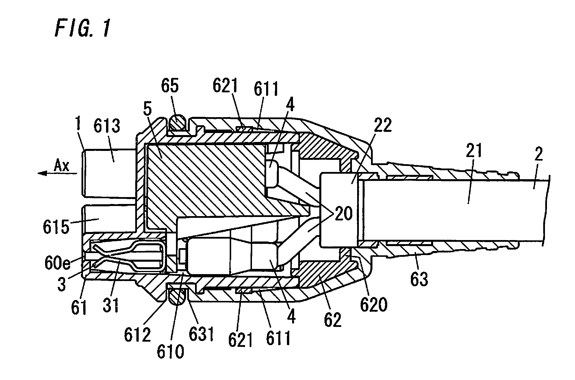
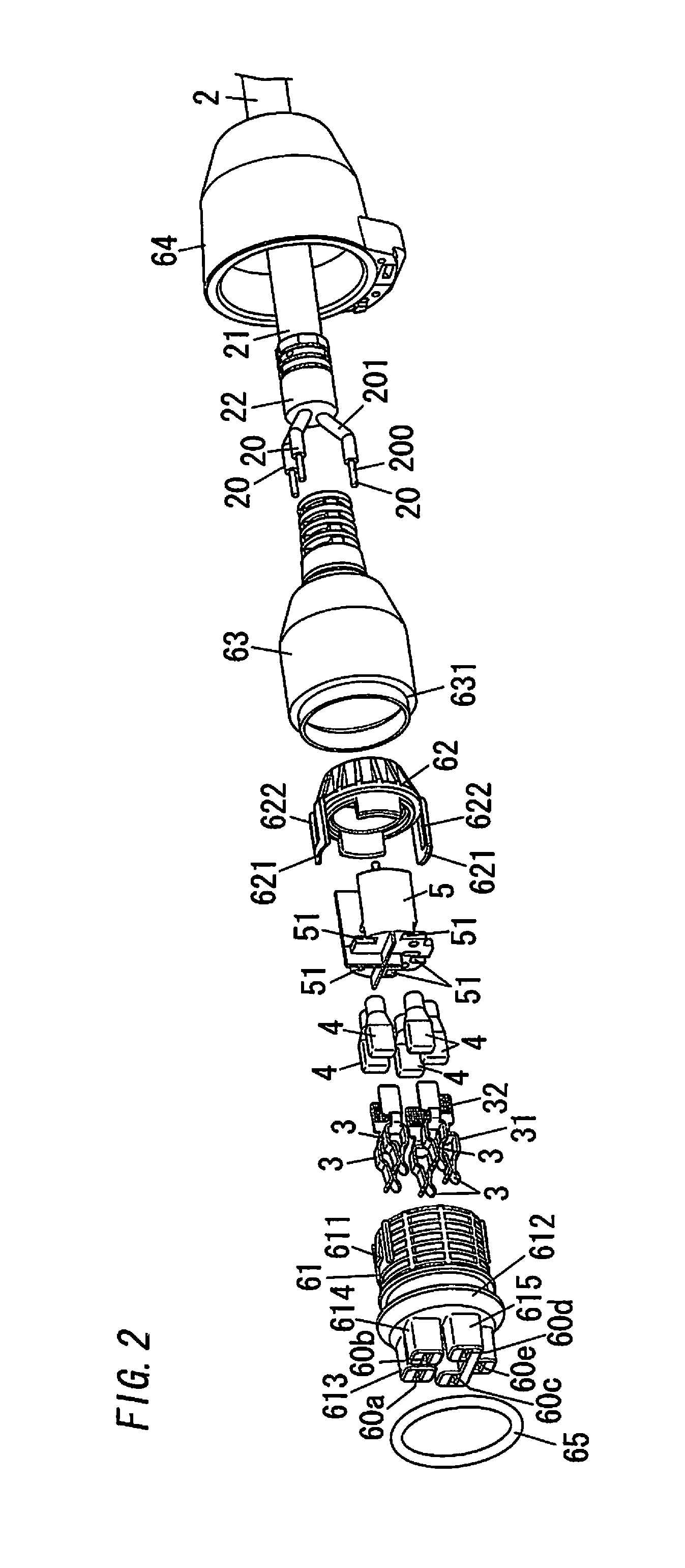
[0019]As shown in FIG. 1 and FIG. 2, a female connector 1 of the present embodiment is installed at an end of a cable 2. The cable 2 includes a plurality of electric wires 20 (three electric wires in an illustrated example) and a sheath 21 which bundles the plurality of electric wires 20. Each of the plurality of electric wires 20 includes a core wire 200 and a cover 201. The core wire 200 is made of conductive material such as copper. The cover 201 is made of insulating material such as synthetic resin, and designed to cover the core wire 200. The cable 2 is provided with a sealing part 22 which has a columnar shape and is designed to seal an end of the sheath 21. The sealing part 22 as described above is formed, for example, by filling synthetic resin into a cylindrical member in a state where the cylindrical member is attached to the end of the sheath 21.

[0020]The fe...


PUM


Abstract

A female connector 1 includes a plurality of contactors 3, a holding body 5, a body 61, and a holder 62. Plurality of contactors 3 are connected to a plurality of electric wires 20 of a cable 2, respectively. Holding body 5 is designed to hold the plurality of contactors 3. Body 61 has a housing recess 610 designed to house the plurality of contactors 3 and holding body 5. Holder 62 is designed to prevent holding body 5 from falling from housing recess 610 by coupling to body 61. Female connector 1 includes a cover 63 formed by double molding so as to cover holder 62 in a state where cable 2 is inserted into holder 62 and where holder 62 and body 61 are coupled to each other. Holder 62 is designed to be in close contact with cable 2 along a whole circumference thereof.

Description

BACKGROUND OF THE INVENTION[0001]1. Field of the Invention[0002]The invention relates generally to female connectors, and more specifically to a female connector formed by double molding.[0003]2. Description of the Related Art[0004]In the past, there has been known a technique of so-called double molding, in which a first resin molded product is insert-molded to a second resin molded product (for example, see Japanese Patent Application Publication No. 2012-146602A).[0005]There has been a female connector, which is installed at an end of a cable in which a plurality of electric wires are bundled. The female connector includes a plurality of contactors, a body and a holder. The plurality of contactors are connected to the plurality of electric wires, respectively. The body is designed to house the plurality of contactors. The holder is formed in an annular shape in which the cable is inserted, and designed to prevent the plurality of contactors from falling by coupling to the body.[0...

Claims


Application Information

Patent Timeline
Patent Type & Authority Applications(United States)
IPC IPC(8): H01R13/52H01R43/00
CPCH01R43/005H01R13/5216H01R13/4367H01R13/504H01R13/5205H01R13/533H01R13/5812H01R24/20
Inventor INAGAKI, NOBORUNAKAMURA, SHINICHIMIKURA, MASAHIKO
Owner PANASONIC INTELLECTUAL PROPERTY MANAGEMENT CO LTD
Why Eureka
Try Eureka