Assembled battery

a battery and assembly technology, applied in the direction of secondary cells, cell components, cell structural combinations, etc., can solve the problems of sometimes appearing thickness errors between battery cells, and achieve the effect of preventing poor connection, large workspace, and insufficient strength

Active Publication Date: 2016-06-16
TOYOTA JIDOSHA KK
View PDF3 Cites 5 Cited by
  • Summary
  • Abstract
  • Description
  • Claims
  • Application Information

AI Technical Summary

Benefits of technology

[0009]In the above assembled battery, it is preferable that the concave portion have an opening part at a bottom part. Thereby, it is possible to prevent a poor connection due to the non-filling of the conductive adhesive and an insufficient strength at a connection part between the bus bar and the circuit board.
[0010]In the above assembled battery, it is preferable that the second connection part be connected with the first connection part via a step part, such that the ...

Problems solved by technology

By the manufacturing tolerance of the battery cells, a...

Method used


Image

  • Assembled battery
  • Assembled battery
  • Assembled battery

Examples


embodiment 1

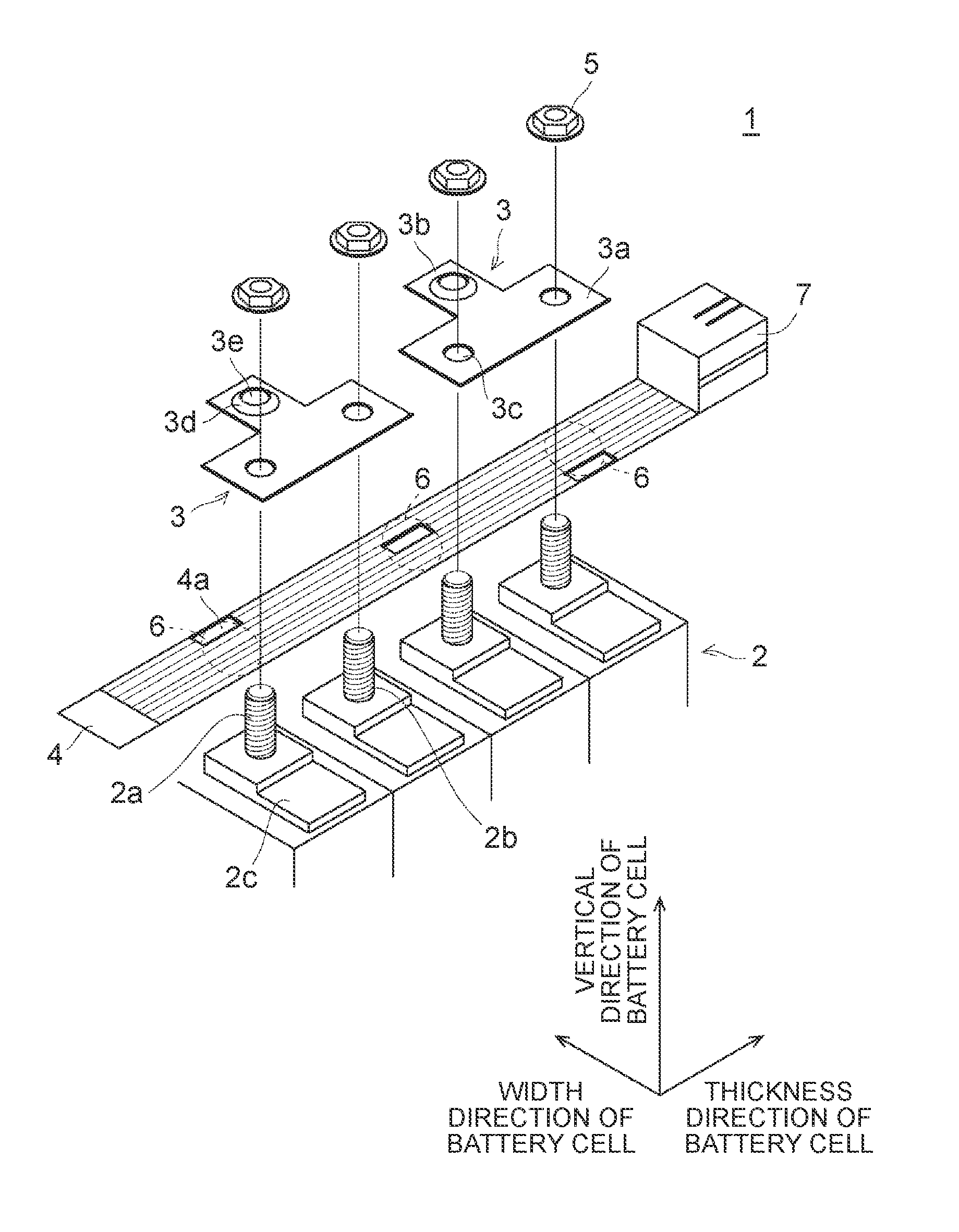
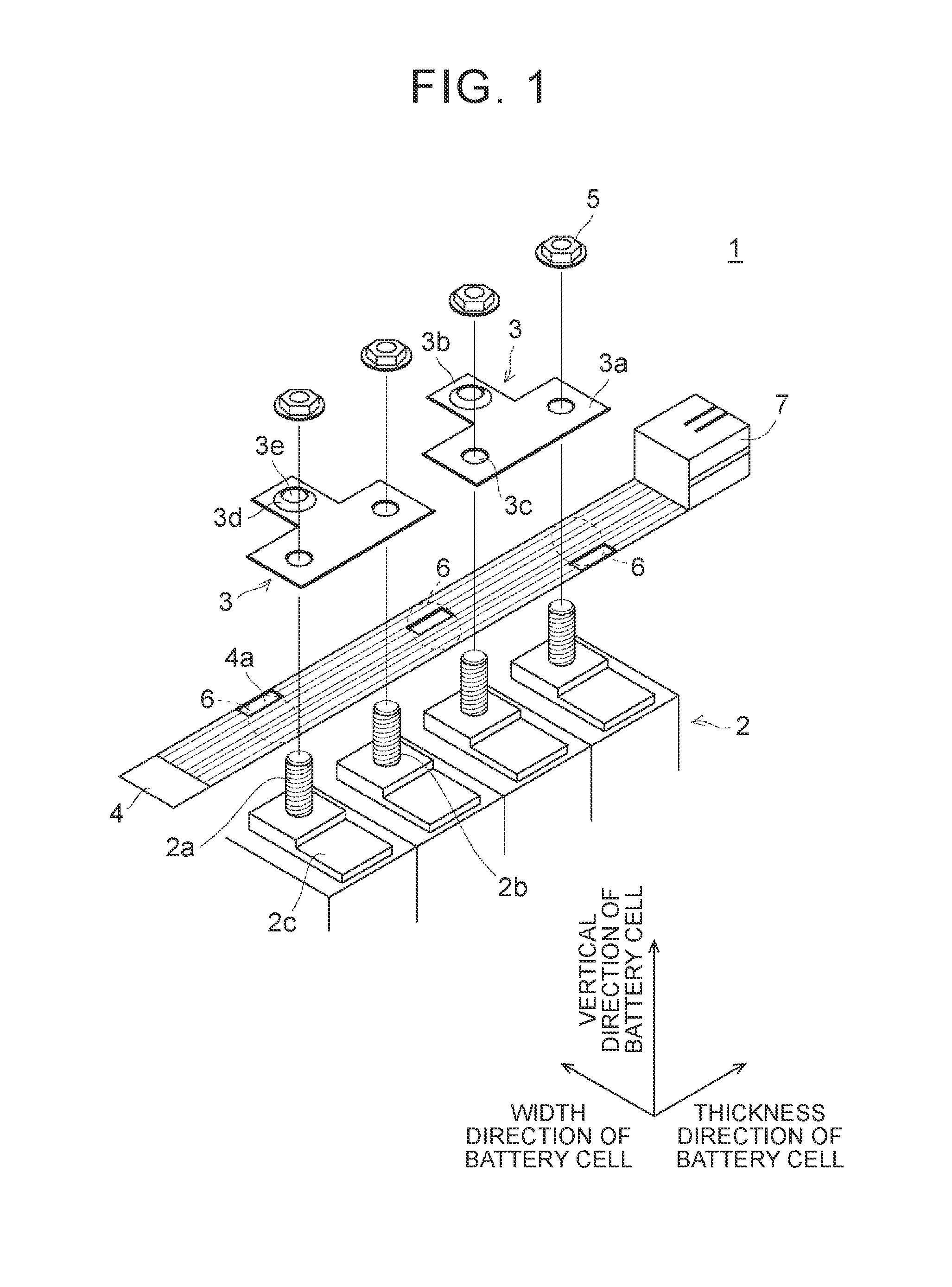
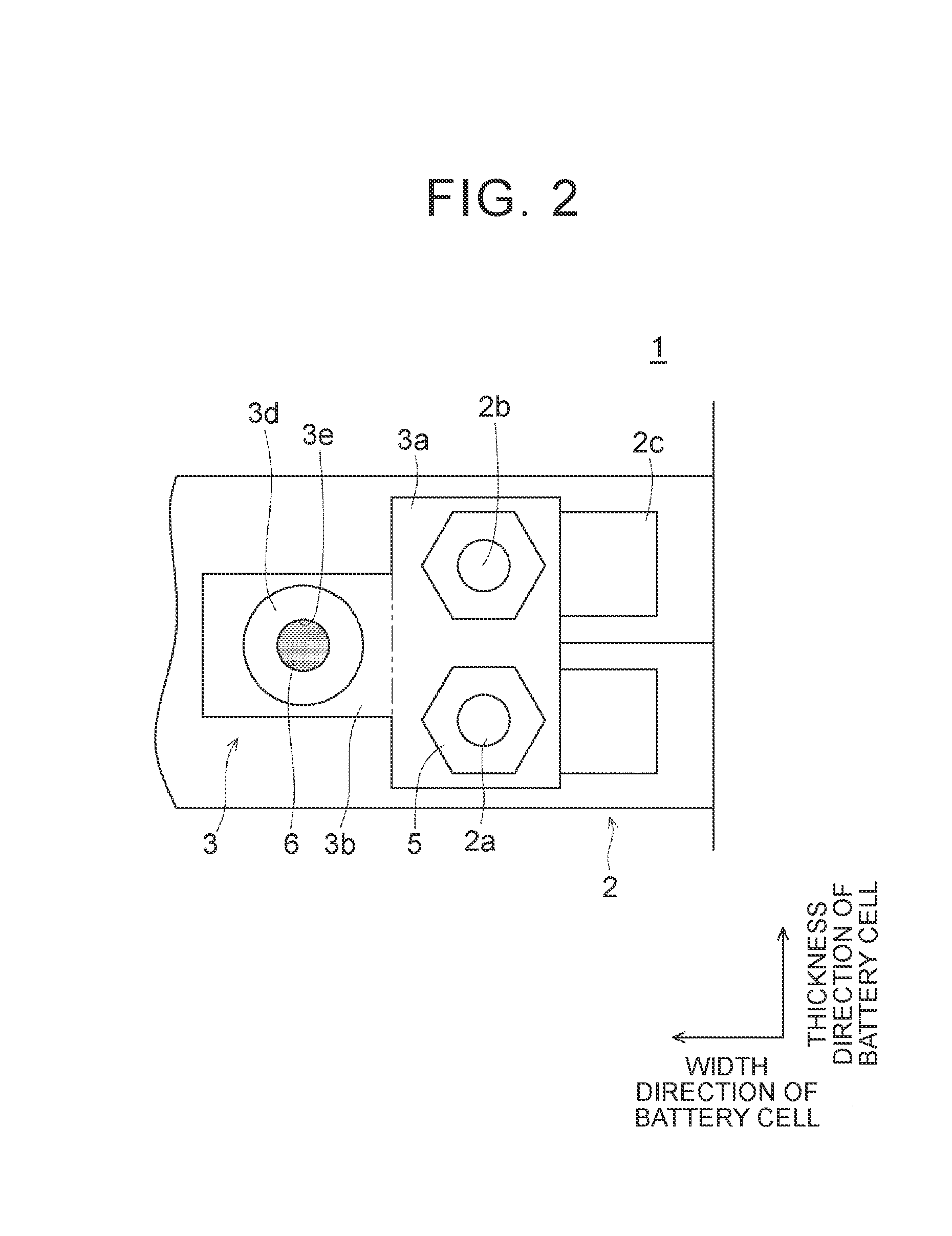
[0025]The configuration of an assembled battery in the embodiment will be described. FIG. 1 is an enlarged exploded view showing an upper part of the assembled battery in the embodiment. FIG. 2 is an enlarged plan view showing the assembled battery in the embodiment. FIG. 3A is a plan view showing a bus bar in the embodiment. FIG. 3B is a lateral view of the bus bar in the embodiment.

[0026]As shown in FIG. 1 and FIG. 2, the assembled battery 1 includes battery cells 2, bus bars 3, and a circuit board 4. The battery cell 2 is a general lithium-ion battery or the like. On the upper surface, an electrode terminal 2a, which is one of a positive electrode and a negative electrode, is provided at one end in the width direction of the battery cell 2, and an electrode terminal 2b, which is the other of the positive electrode and the negative electrode, is provided at the other end.

[0027]As shown in FIG. 1, the electrode terminals 2a, 2b in the embodiment, which are rod screws, protrude upwa...

embodiment 2

[0041]The bus bar 3 in the Embodiment 1 is formed as a flat plate member, but is not limited to this. That is, in a bus bar 31 shown in FIG. 6, a second connection part 31b is connected with a first connection part 31a via a step part 31c, such that the interval between the second connection part 31b and the upper surface of the battery cell 2 is wider. In other words, the bus bar 31 is bent such that the interval between the second connection part 31b and the upper surface of the battery cell 2 is wider than the interval between the first connection part 31a and the upper surface of the battery cell 2. Thereby, it is possible to secure a large workspace for connecting the circuit board 4 with the bus bar 31. Here, in FIG. 6, the same elements as the bus bar 3 in Embodiment 1 are denoted using the same reference characters.

embodiment 3

[0042]The concave portion 3d in Embodiment 1 and Embodiment 2 has a truncated cone shape, but is not limited to this. That is, as shown in FIG. 7A and FIG. 7B, a concave portion 41d of a bus bar 41 may be formed in a truncated square pyramid shape. Further, as shown in FIG. 8A and FIG. 8B, a concave portion 42d of a bus bar 42 may be formed in a hemisphere shape. In short, the shape is not particularly limited, as long as the conductive adhesive 6 can be contained. Here, in FIG. 7A, FIG. 7B, FIG. 8A and FIG. 8B, the same elements as the bus bar 3 in Embodiment 1 are denoted using the same reference characters.


PUM


Abstract

An assembled battery includes a plurality of battery cells, a bus bar that electrically connects the battery cells with each other, and a circuit board that is electrically connected with the battery cells. The bus bar has a first connection part that is electrically connected with the battery cells, and a second connection part that is electrically connected with a connection part of the circuit board via a conductive adhesive. The second connection part has a concave portion that contains the conductive adhesive.

Description

INCORPORATION BY REFERENCE[0001]The disclosure of Japanese Patent Application No. 2014-251174 filed on Dec. 11, 2014 including the specification, drawings and abstract is incorporated herein by reference in its entirety.BACKGROUND OF THE INVENTION[0002]1. Field of the Invention[0003]The invention relates to an assembled battery, and particularly, relates to an assembled battery including a plurality of battery cells, a bus bar that electrically connects the battery cells with each other, and a circuit board that is electrically connected with the plurality of battery cells.[0004]2. Description of Related Art[0005]In an assembled battery in which a plurality of battery cells are connected, a circuit board for detecting the respective voltages of the battery cells and equalizing the respective voltages of the battery cells is electrically connected with the battery cells. For example, in an assembled battery in Japanese Patent Application Publication No. 2003-45409 (JP 2003-45409 A), ...

Claims


Application Information

Patent Timeline
IPC IPC(8): H01M2/20H01M10/48H01M10/42H01M50/528H01M50/507H01M50/569
CPCH01M2/202H01M2010/4271H01M10/482H01M10/425H01M50/569H01M50/507Y02E60/10
Inventor OKIGA, HIROSHI
Owner TOYOTA JIDOSHA KK
Why Eureka
Try Eureka