Integrated sensor

a sensor and integrated technology, applied in the field of electric sensors, can solve the problems of low bandwidth, inconvenient installation, and large size of typical current sensors, and achieve the effect of reducing the size of the typical current sensor, and reducing the cost of installation

Active Publication Date: 2007-08-21
ALLEGRO MICROSYSTEMS INC
View PDF46 Cites 208 Cited by
  • Summary
  • Abstract
  • Description
  • Claims
  • Application Information

AI Technical Summary

Benefits of technology

This patent describes a device that includes a layer for detecting changes in magnetic fields. It also mentions that the device could have various functions depending on its design, including measuring electric currents and signals. Additionally, it suggests that there might be multiple layers of conductors within the device. Overall, the technical effect of this patent is providing a versatile tool for sensing magnetic fields with potential uses in many industries.

Problems solved by technology

The technical problem addressed in this patent text is the need for a current sensor that is smaller and more accurate than conventional current sensors. The current sensors described in the text suffer from being large and having low bandwidth, and they also suffer from variations in position between the primary conductor, magnetic field transducer, and secondary conductor. The patent aims to provide a solution for reducing the size and improving the accuracy of current sensors.

Method used


Image

  • Integrated sensor
  • Integrated sensor
  • Integrated sensor

Examples


Embodiment Construction

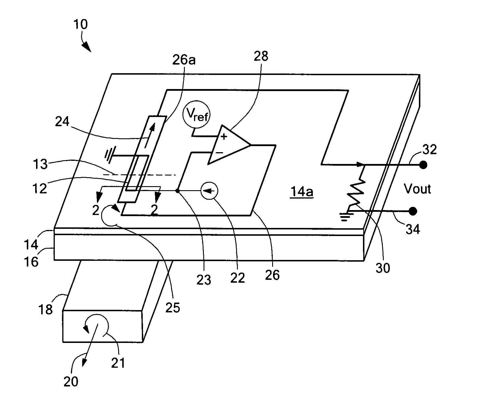
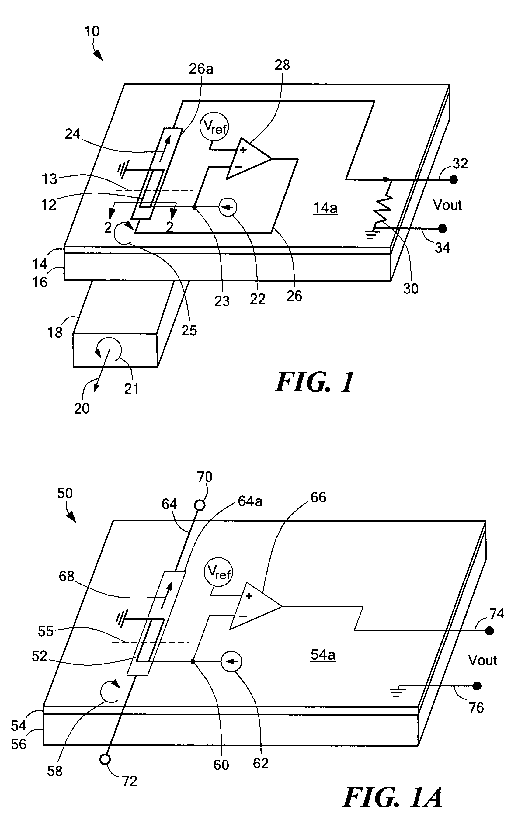
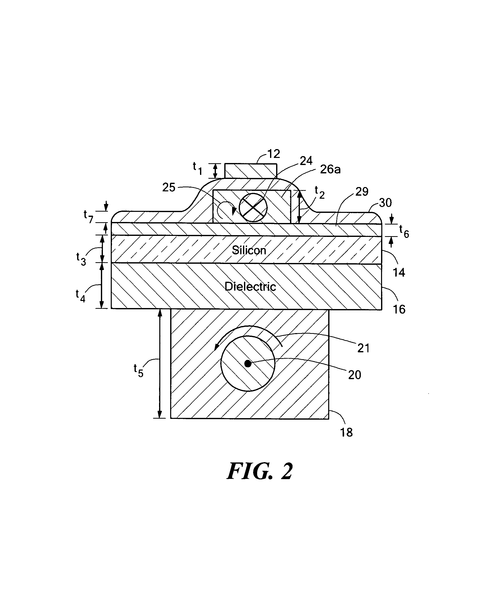
[0031]Referring to FIG. 1, an electronic circuit 10 includes a silicon substrate 14, a magnetic field transducer 12 disposed over a surface 14a of the silicon substrate, and a conductor 26 disposed over the surface 14a of the silicon substrate proximate to the magnetic field transducer 12. With this arrangement, an integrated circuit is provided which is suitable for various applications, such as a current sensor (FIGS. 1, 1A, 3 and 4), a magnetic field sensor (FIGS. 6 and 6A), and a signal isolator (FIGS. 7 and 7A).

[0032]The electronic circuit 10 can be used in open loop configurations in which a current passes through the conductor 26 (see FIG. 1A) or in closed loop configurations in which a further conductor 18 is also used. The conductor 18 is isolated from the silicon substrate 14 by a dielectric 16, as shown. In closed loop applications, in which both the conductor 18 and conductor 26 are used, the conductor 18 is referred to as the primary conductor and conductor 26 is referr...


PUM


Abstract

An integrated sensor includes a magnetoresistance element electrically coupled to a device disposed on or integrated in a silicon substrate. A conductor is provided proximate to the magnetoresistance element. The integrated sensor can be used to provide various devices, such as a current sensor, a magnetic field sensor, or an isolator. Further, the integrated sensor can be used in an open loop configuration or in a closed loop configuration in which an additional conductor is provided. The magntoresistance element may be formed over the silicon substrate or on a separate, non-silicon substrate. Also described is an integrated sensor comprising a substrate, a magnetic field transducer disposed over a surface of the substrate, and a conductor disposed over the surface of the substrate proximate to the magnetic field transducer. The magnetic field transducer can be a Hall effect transducer or a magnetoresistance element.

Description


Claims


Application Information

Patent Timeline
Owner ALLEGRO MICROSYSTEMS INC
Why Eureka
Try Eureka