Child safe cord lock

a cord lock and child-safe technology, applied in the field of cord locks, can solve the problems of children becoming entangled in cords, affecting the appearance of blinds,

Active Publication Date: 2007-08-28
HUNTER DOUGLAS INC
View PDF11 Cites 62 Cited by
  • Summary
  • Abstract
  • Description
  • Claims
  • Application Information

AI Technical Summary

Benefits of technology

[0006]We provide a cord lock that retains the lift cords in a manner so that no lift cord can be pulled away from the window covering material in a fully lowered blind. Yet, the cord lock readily releases the cord when an operator pulls on the lift cords to raise the blinds. To lower the blind an operator pulls a release cord that extends from the cord lock.
[0007]Our cord lock has a generally rectangular housing containing at least one cam spaced apart from a surface over which one or more lift cords pass. In the preferred embodiments the surface is a wheel and there is one cam and one wheel for each lift cord. The cams can rotate about a first axis from at least one unlocked position to a locked position, and from the locked position to the unlocked position. The surface is spaced apart from the cam such that a cord passing over the surface will be pressed against the surface and restrained when the cam is in the locked position, and the cord can freely pass over the surface in at least one direction when the cam is in the at least one unlocked position.
[0009]A release cord is attached to the cam lock in a manner so that pulling the release cord moves the cam lock to engage and move the cams from the locked position to a release position in which the lift cords can freely move through the cord lock. One or more springs are attached to the cam lock, to the axle carrying the cams or directly to the cams, biasing the cams to the locked position. The spring has a strength that enables the cams to move from the locked position to the unlocked positions when an operator pulls the lift cords to raise the blind or pulls the release cord to lower the blind.

Problems solved by technology

But, typically those cord locks do not lock the cords in place when the blind is fully lowered.
Indeed, some children have become entangled in a cord loop created in this way and have been strangled.
A similar problem can also occur in pleated shades and roman shades.
Even though the cord stops that have been used are made from clear plastic, they are quite noticeable and detract from the appearance of the blind.
Fabricators and installers who install cord stops on their blinds must spend more time on each job thereby increasing the cost of the installation.

Method used


Image

  • Child safe cord lock
  • Child safe cord lock
  • Child safe cord lock

Examples


Embodiment Construction

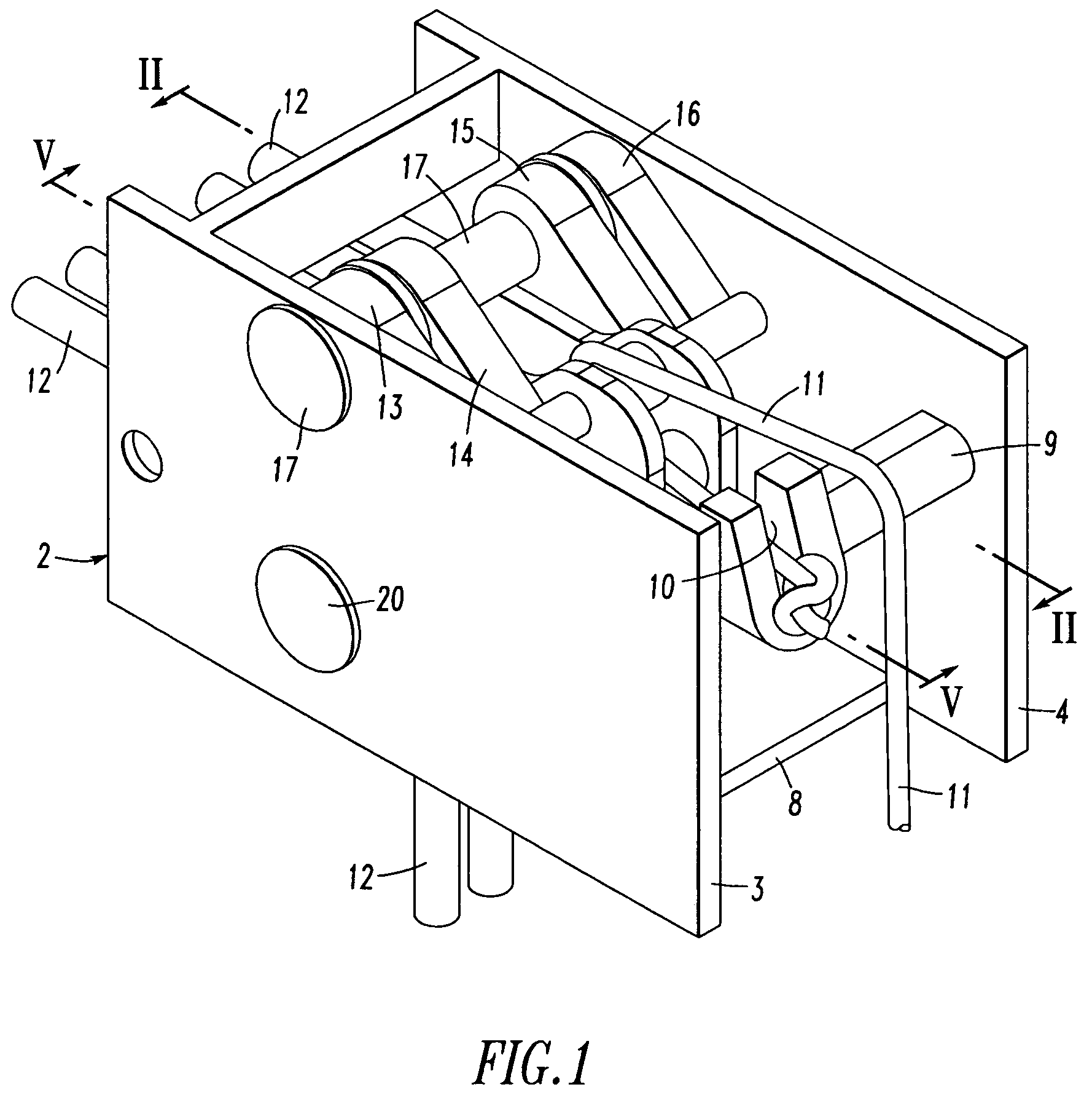
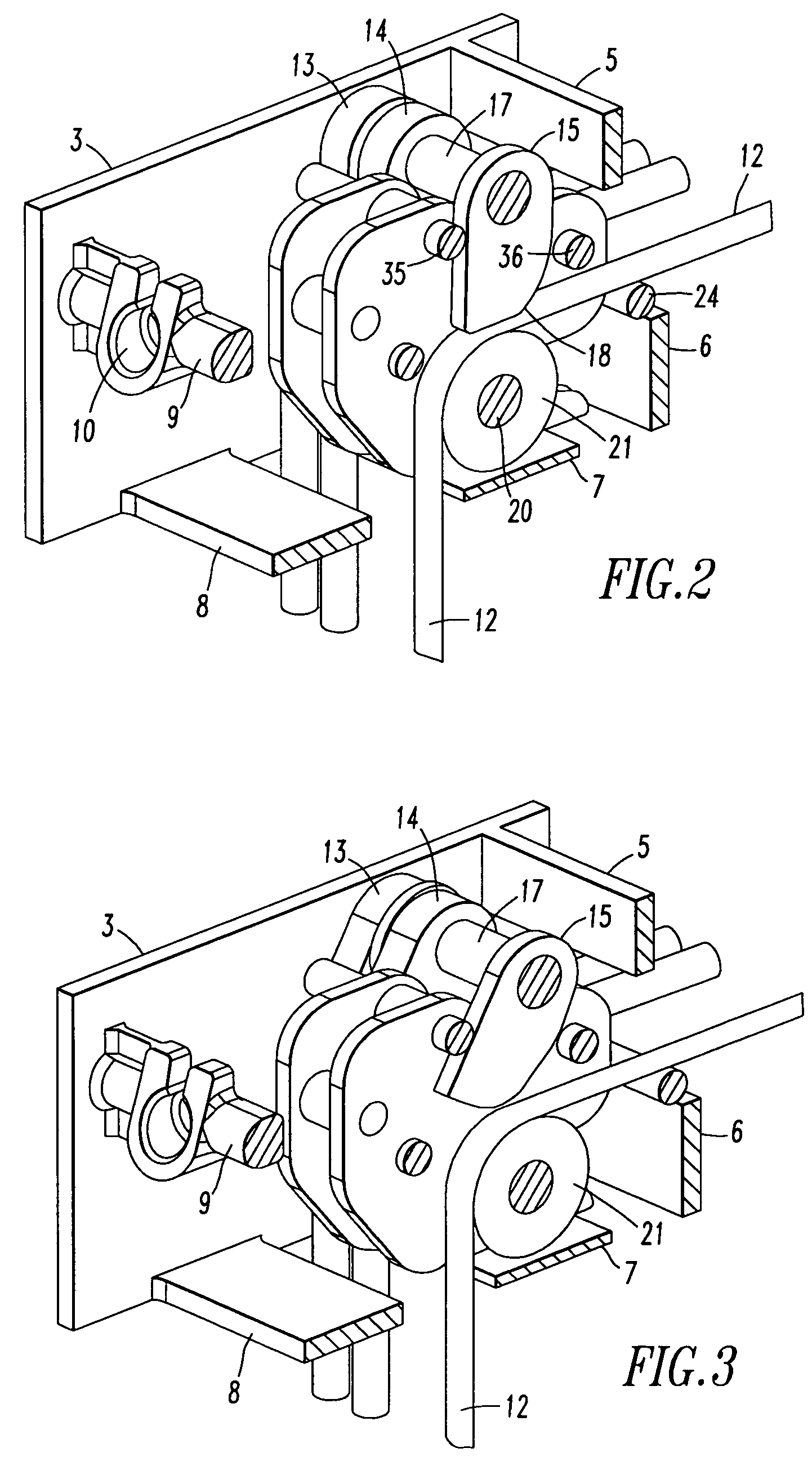
[0028]A first present preferred embodiment of our cord lock 1, shown in FIGS. 1 through 6, has a housing 2 formed from two spaced apart parallel sides 3 and 4 held together by front walls 5 and 6, bottom walls 7 and 8 and spacer 9. An inverted keyhole slot 10 is provided in the spacer 9 through which a release cord 11, shown only in FIG. 1, passes. The cord lock shown in FIGS. 1 though 6 is configured to accommodate four lift cords 12. As will be seen, other configurations could be provided to receive two, three, five, six or even more cords. However, for blinds having eight or more lift cords we prefer to use two or more cord locks.

[0029]The operation of the cord lock can best be understood with reference to FIGS. 2, 3, and 4. Within the cord lock housing 2 we provide four cams 13, 14, 15 and 16 on a common pin 17 that passes through the housing. There is one cam for each lift cord 12. All of the cams rotate on a common axis defined by pin 17. We prefer to provide teeth or a serrat...


PUM


Abstract

A cord lock for window coverings has one or more cams adjacent a surface over which a one or more lift cords travel. The cams are spring biased to a locked position in which they press the lift cords against the surface. A cam lock with a release cord is provided which engages and moves the cams from a locked position to an unlocked position in which the lift cords are free to move through the cord lock. The cord lock is always in a locked position whenever neither the lift cords are being pulled to raise the blind nor the release cord is being pulled to lower the blind.

Description

FIELD OF INVENTION[0001]The present invention relates to a cord lock for window blinds which are raised and lowered by lift cords such as venetian blinds.BACKGROUND OF THE INVENTION[0002]Venetians blinds have a headrail, a bottom rail and a set of slats carried on ladders that extend from the headrail to the bottom rail. Lift cords extend from the bottom rail through or adjacent the slats and into the headrail. The lift cords may be wound and unwound on an axle within the headrail, but more commonly pass through a cord lock in the headrail and exit the headrail at one end. Conventional cord locks will restrain the lift cords when the blind is in a fully raised, or partially lowered, position. But, typically those cord locks do not lock the cords in place when the blind is fully lowered. Consequently, anyone can grasp a lift cord of a fully lowered blind and pull the lift cord away from the blind until the end of the lift cord, which typically has a tassel, reaches the end of the hea...

Claims


Application Information

Patent Timeline
Patent Type & Authority Patents(United States)
IPC IPC(8): E06B9/324
CPCE06B9/324Y10T24/394Y10T24/3944
Inventor JUDKINS, RENJUDKINS, LANDON LEE
Owner HUNTER DOUGLAS INC
Why Eureka
Try Eureka