
Method and device for reprofiling railway wheels

a railway wheel and wheel bearing technology, applied in the direction of grinding machines, turning apparatuses, milling equipment, etc., can solve the problems of high weight, disadvantageous disassembly and remounting of wheelsets, wear of wheels and brake disks of railway vehicles, etc., and achieve the effect of sufficient precision

Inactive Publication Date: 2007-08-28
HEGENSCHEIDT MFD
View PDF19 Cites 10 Cited by
  • Summary
  • Abstract
  • Description
  • Claims
  • Application Information

AI Technical Summary

Benefits of technology

[0005]From this, the object of the present invention results, of providing a universal wheelset machine tool which may be used at different locations as necessary. In this way, the transport of railway wheels, wheelsets, locomotives, trains, or cars is to be reduced and, simultaneously, the machine is to operate with sufficient precision for reprofiling of wheel disks or machining of brake disks. The machine is to be provided with its own power supply devices, and it is also to be connectable to already existing power supply devices of specialized workshops. In particular, the machine is to be used for machining both individual, uninstalled railway wheels and / or wheelsets and railway wheels or wheelsets which remain installed in the railway vehicle.
[0021]In a further embodiment, the machine tool is attached to a vehicle. This vehicle may be a road vehicle or a railway vehicle. The machine tool is conveyed to the location of its use with the aid of such a vehicle. In this case, further devices may also be present on the vehicle, which supply the machine tool with the necessary power, whether it is electrical power or power of a pressure medium, such as hydraulics or pneumatics. In addition, it is advantageous if the vehicle, using which the machine tool is transported, simultaneously also has hoists, using which a railway wheel, a truck, or a wheelset may be lifted and / or lowered for machining on the machine tool. If the machine tool is not attached, a ramp may be provided, via which the machine tool may be moved off of the transport vehicle, in order to be placed at the location at which the machining is to be performed. Even in such a case, the power supply device for the machine tool may also be carried by the transport vehicle, however, it is also possible to connect the machine tool to already existing infrastructures for power supply of a workshop.
[0023]It is also advantageous to measure the railway wheel and / or the wheel disk to be machined before the machining and also after the machining. In this way, the success of machining is ensured. Mechanical caliper elements or optical triangulation calipers suggest themselves as measurement instruments.

Problems solved by technology

The wheels and brake disks of railway vehicles wear out due to material wear, plastic deformation, and braking and acceleration processes.
However, the outlay for dismounting and remounting the wheelset is disadvantageous in this case, and this is particularly true for the wheelsets of traction vehicles, where it is required that the entire vehicle be operationally inspected after uninstallation of a traction wheelset.
Since they are designed for the machining of heavy vehicles using high metal removing forces, they also have a correspondingly high weight.
For railway and local service companies which carry out their business using only a few vehicles, the investment for a wheelset machine tool, whether it is a surface or an underfloor machine tool, is hardly cost effective.
However, even in the main railways, there are only a few workshops which are equipped with wheelset machine tools.
Sometimes, the capacity of the installed wheelset machine tools is not sufficient to cover the peak demand.
Replacement times, non-availability, and transportation and logistics costs are added to the actual machining cost for the wheelsets.

Method used


Image

  • Method and device for reprofiling railway wheels
  • Method and device for reprofiling railway wheels

Examples


Embodiment Construction

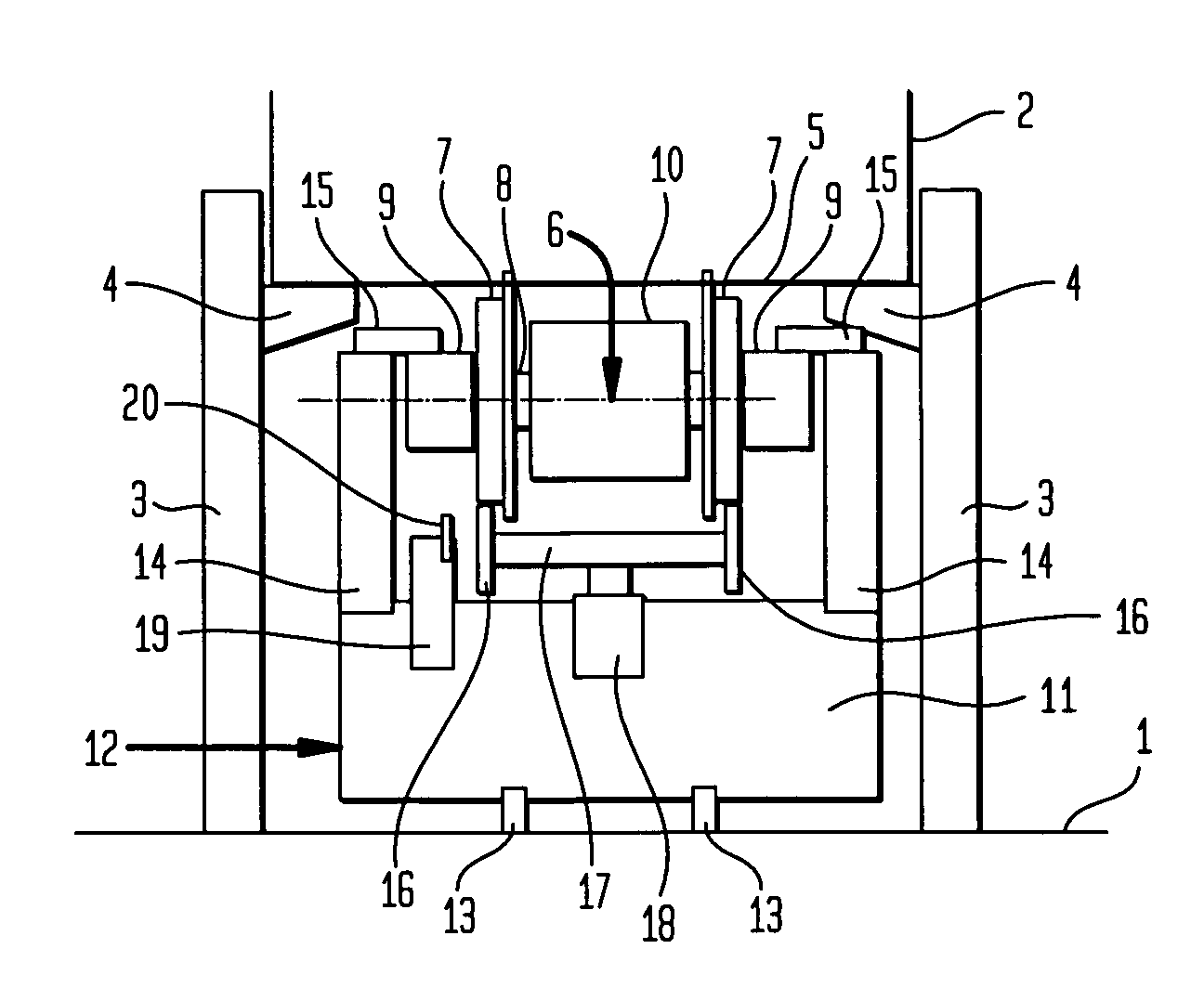
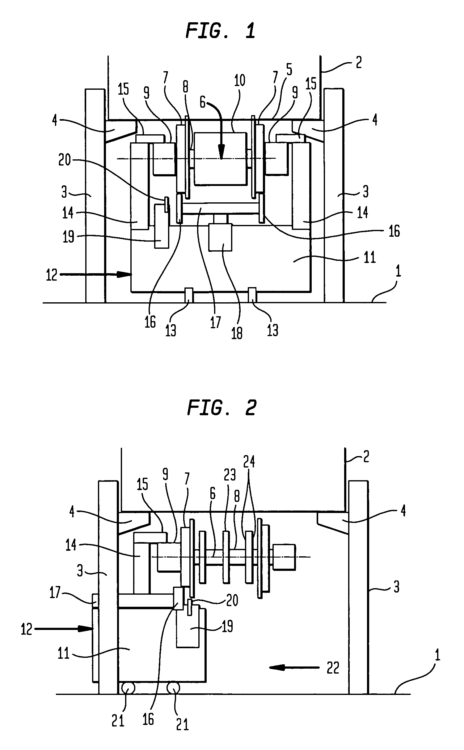
[0026]A railway vehicle 2 is on stands above workshop floor 1 in FIG. 1. The vehicle is put on stands with the aid of perpendicular columns 3 which stand laterally next to railway vehicle 2 on workshop floor 1. Railway vehicle 2 itself rests on brackets 4, whose height may be adjusted vertically along columns 3. Bottom edge 5 of the car body of railway vehicle 2 is at a height between 1 and 2.5 m above workshop floor 1.

[0027]FIG. 1 shows railway vehicle 2 viewed from its front end. A wheelset 6 is connected to railway vehicle 2, which is intended for the purpose of having both its wheel disks 7 run in a track. Wheel disks 7 are connected to wheelset shaft 8 so that they rotate together and are rotatably mounted outside both wheel disks 7 in axle bearing housings 9. In the present example, wheelset 6 of a traction vehicle 2 is shown, on whose wheelset shaft 8 a drive motor 10 is also positioned. Wheelset 6 is connected to railway vehicle 2 via both bearing housings 9; the details of ...


PUM

PropertyMeasurementUnit
heightaaaaaaaaaa
heightaaaaaaaaaa
plastic deformationaaaaaaaaaa

Abstract

The present invention relates to a method for reprofiling wheel disks (7) or brake disks of a railway wheel or wheelset (6), rotatably mounted in bearing housings (9), by machining using a machine tool (12), which is designed to be portable, a wheel disk (7) of the railway wheel or the wheelset (6) being pressed against backup rolls (16) on its circumference by a clamping element (14, 15), which engages on at least one bearing housing (9), at least one of the backup rolls setting the railway wheel or the wheelset (6) into rotation, while simultaneously a tool (20) machines one of the wheel (7) or brake disks. The invention also relates to a machine tool (12) for carrying out the method. This machine tool (12) has a portable support frame (11) having a clamping element (14, 15) for engaging on a closed inner and / or outer bearing housing (9) of the railway wheel or wheelset (6), and at least one backup roll (16), which may be pressed against the outer circumference of the wheel disk (7), on whose bearing housing(s) (9) the clamping element (14, 15) engages, at a mutual distance to one another opposite to the clamping element (14, 15), a drive for at least one of the backup rolls (16), and a tool (20) for machining wheel (7) or brake disks (23) of the railway wheel or wheelset (6).

Description

BACKGROUND OF THE INVENTION[0001]The present invention relates to a method and a machine for machining railway wheels. The machining extends not only to the reprofiling of wheels of individual wheel trucks, but also to the reprofiling of the wheels of wheelsets. It also extends to the reprofiling of brake disks, whether they are on individual wheel trucks or on the wheelsets of other trucks. The requirement for carrying out the machining according to the present invention is that the affected railway wheel and / or the wheelset is rotatably mounted in axle bearing housings. In this case, the individual wheel and / or the wheelset to be machined may be in the uninstalled state, but the individual wheel and the wheelset may also be machined in the installed state.[0002]The wheels and brake disks of railway vehicles wear out due to material wear, plastic deformation, and braking and acceleration processes. For these reasons, they have to be reprofiled from time to time, and this is typical...

Claims


Application Information

Patent Timeline
Patent Type & Authority Patents(United States)
IPC IPC(8): B24B29/00B24B5/00B23B5/02B23B5/28B23B5/32B23C1/20B24B5/46
CPCB23B5/32B24B5/46Y10T82/185Y10T409/305656
Inventor BOMS, MANFREDHAUSCHILD, GEORGHEIMANN, ALFREDHOCK, RALFREICHE, HANS-JOACHIM
Owner HEGENSCHEIDT MFD
Learn More