Synthetic blown insulation

a technology insulation layer, which is applied in the field of synthetic blown insulation, can solve the problems of exceeding the thermal insulation properties, difficult to blow through conventional equipment, and too heavy and dense to be considered downlike, and achieves the effects of reducing the poke-through of covering fabrics, wide flexibility, and low cos

Active Publication Date: 2007-08-28
PRIMALOFT
View PDF35 Cites 12 Cited by
  • Summary
  • Abstract
  • Description
  • Claims
  • Application Information

AI Technical Summary

Benefits of technology

[0024]It is therefore a principal object of the invention to provide for an insulation material which has a superior thermal, loft, comfort and water absorption characteristics exhibited by some of the aforesaid references, however, through the use of a fir-tree structure more similar to natural down whilst being in a blowable form.
[0025]It is a further object of the invention to provide for an insulation material that is a substitute for natural down at a lower cost.
[0026]A further object of the invention is to provide for a cohesive insulation material in which bonding of filaments reduces the fiber poke-through of covering fabrics.
[0027]A still further object of the invention is to provide for a method for producing such an insulation material which offers wide flexibility to vary the specification and properties of the resultant materials.

Problems solved by technology

Prior efforts to develop a feasible material have often yielded those with a structure dissimilar from real down, are too heavy and dense to be considered down-like, and / or are difficult to blow through conventional equipment.
This material approaches, and in some cases might even exceed the thermal insulating properties of natural down.
From a mechanical standpoint, the use of extremely fine fibers may result in concerns for rigidity and strength that make them difficult to produce, manipulate and use.
Recovery properties of such a synthetic insulator material are enhanced at larger fiber diameters, but an increase in the large fiber component will seriously reduce the thermal insulating properties overall.
The problems associated with mechanical stability of fine fiber assemblies are more of a concern in the wet condition since surface tension forces associated with the presence of capillary water are considerably greater than those due to gravitational forces or other normal use loading and they have a much more deleterious effect on the structure.
However, prior art clusters often are generally hand fabricated in a slow, tedious, batch process.
Furthermore, some of the prior art materials are not easily blowable materials which can be used with conventional manufacturing equipment.

Method used


Image

  • Synthetic blown insulation
  • Synthetic blown insulation
  • Synthetic blown insulation

Examples


Embodiment Construction

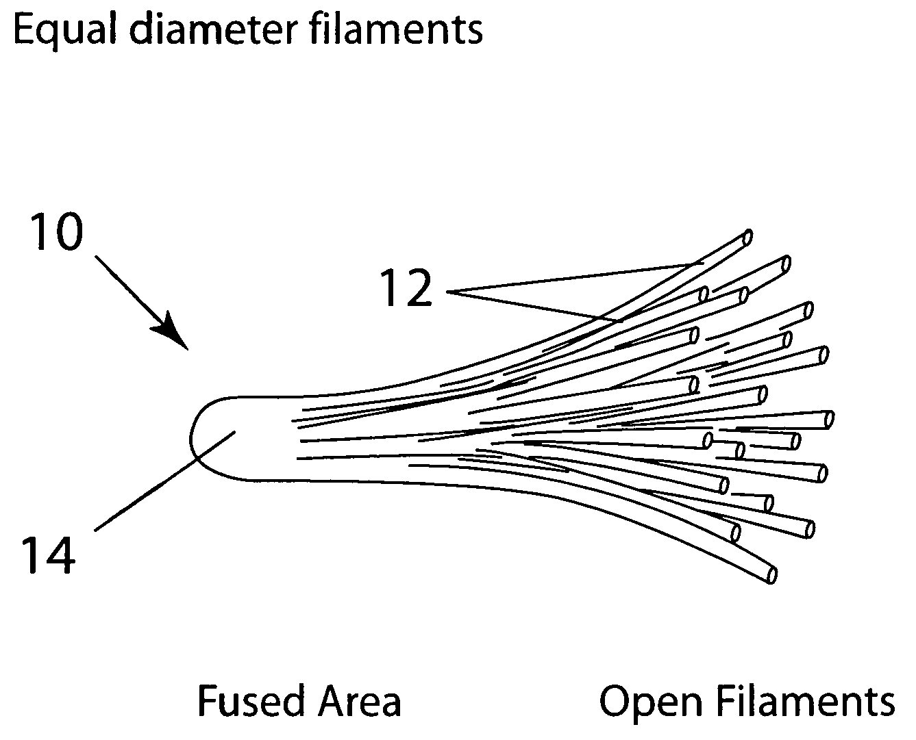
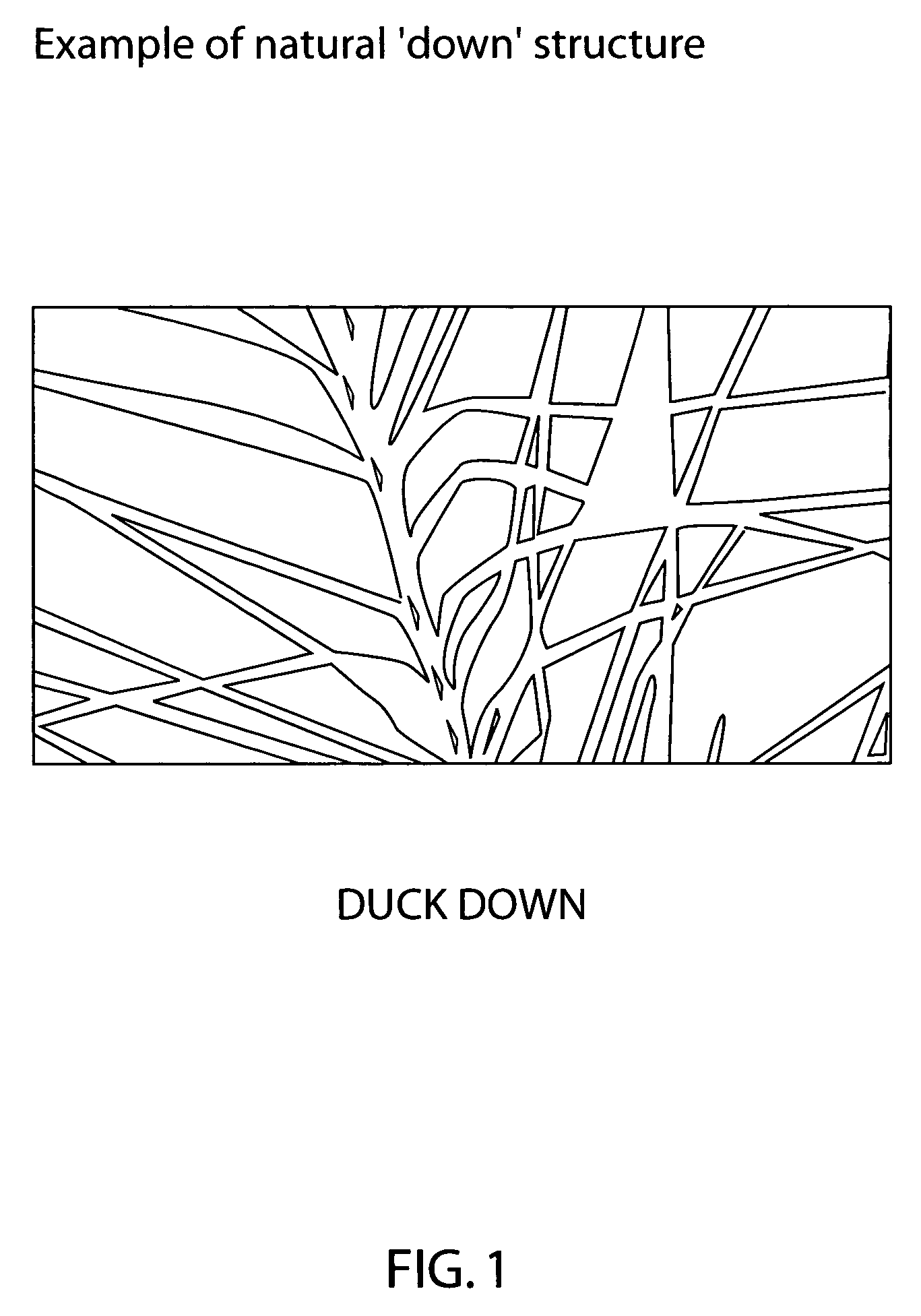
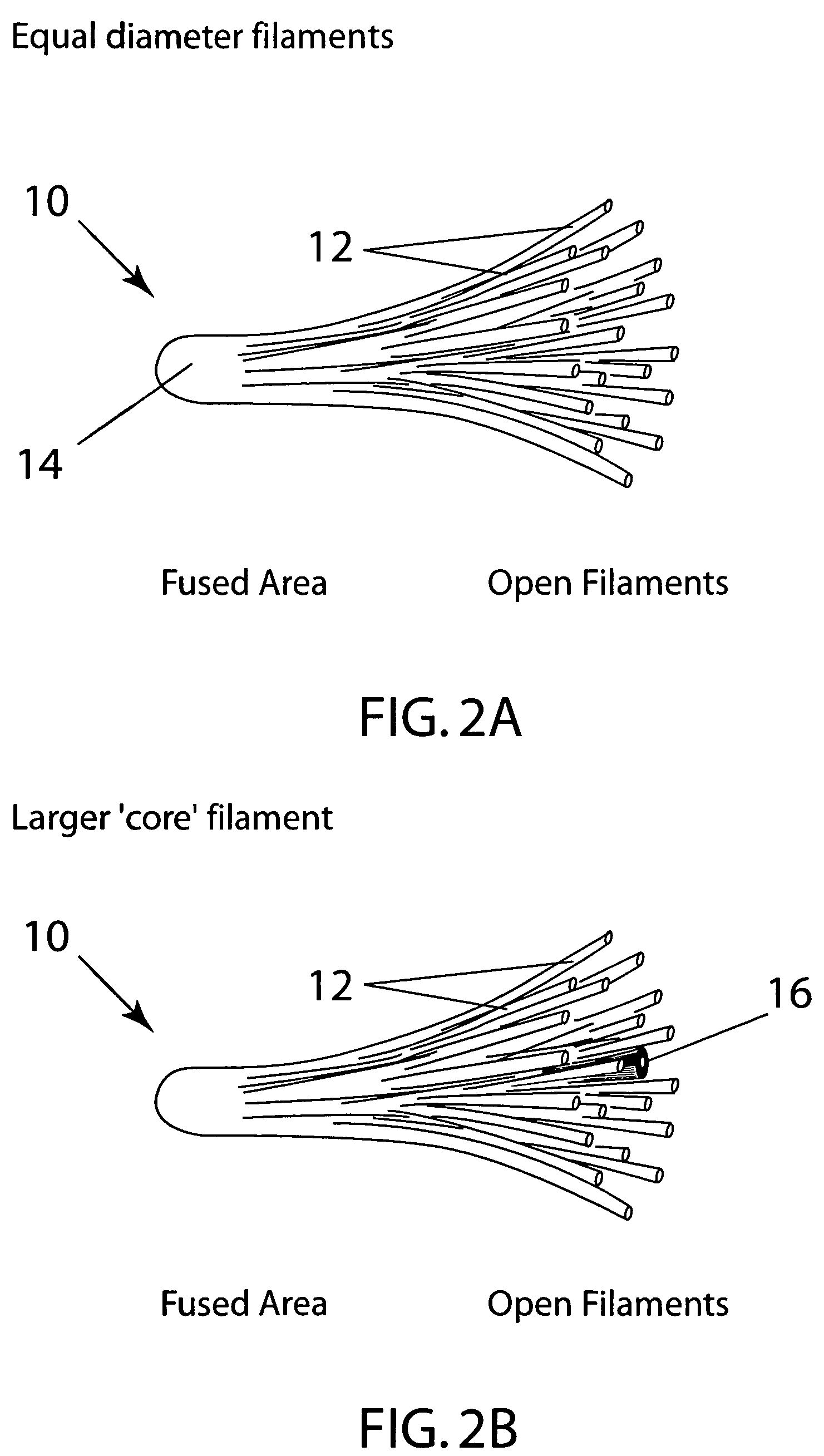
[0035]Turning now more particularly to the drawings, FIG. 2A shows generally the insulation material of the present invention which is in a blowable form. The insulation structure 10 comprises a number of individual filaments 12 joined or fused at one end 14 and open at the opposite end. That is, the insulation structure 10 comprises a fir-tree like or dendritic structure, similar to the structure of the natural down fiber shown in FIG. 1.

[0036]In this connection, the insulation structure 10 may have all filaments 12 of equal diameter as shown in FIG. 2A, or alternatively, a larger diameter core filament 16 surrounded by a plurality of open filaments 12 of smaller diameter as shown in FIG. 2B. In addition, the number and length of the filaments 12, 16 may be varied. Also, the insulation structure 10 may have straight filaments as shown in FIGS. 2A and 2B, or alternatively, crimped filaments (not shown).

[0037]The insulation structure 10 may comprise a wide range of thermoplastic mate...


PUM

PropertyMeasurementUnit
diameteraaaaaaaaaa
densityaaaaaaaaaa
diameteraaaaaaaaaa

Abstract

An insulation material having insulative properties of a synthetic down, while have a fir-tree structure more similar to natural down, and being in a blown form. The blowable insulation material is composed of plural units each having a number of filaments that are fused at one end of the unit and are open at an opposite end.

Description

FIELD OF THE INVENTION[0001]The present invention is directed towards an insulation material, particularly a material having a fir-tree structure similar to natural down whilst also being in a blowable form.BACKGROUND OF THE INVENTION[0002]There have been many attempts to achieve an insulating material having a down-like structure and qualities for use in insulating articles such as clothing, sleeping bags, comforters, and the like. Prior efforts to develop a feasible material have often yielded those with a structure dissimilar from real down, are too heavy and dense to be considered down-like, and / or are difficult to blow through conventional equipment.[0003]These include the following by way of example:[0004]U.S. Pat. No. 988,010 is a labor intensive means of producing a material described as simulating a feather. While twisting is used to achieve the divergence or “fanning” of the individual filaments, this patent teaches two separate components to make a “feather”.[0005]U.S. Pa...

Claims


Application Information

Patent Timeline
Patent Type & Authority Patents(United States)
IPC IPC(8): D04H1/00A41G11/00D04H1/54B68G1/00D04D7/06
CPCA41G11/00B68G1/00Y10T428/2913Y10T428/2984Y10T428/2924Y10T428/2964Y10T428/2929Y10T428/2395Y10T428/249924Y10T428/23943D04H1/00
Inventor DAVIS, TRENT W.LASKORSKI, VICTOR P.
Owner PRIMALOFT
Why Eureka
Try Eureka