
Process field device with radio frequency communication

Active Publication Date: 2007-08-28
ROSEMOUNT INC
View PDF104 Cites 107 Cited by
  • Summary
  • Abstract
  • Description
  • Claims
  • Application Information

AI Technical Summary

Benefits of technology

The patent describes a device used in industrial control systems that can connect to a two-wire control loop to receive power and data. The device has RF circuitry for wireless communication. The device is powered by the two-wire control loop, which provides all the power needed for the RF circuitry. The technical effect of this invention is that it allows for wireless communication in industrial control systems without the need for an additional power source.

Problems solved by technology

However, the majority of field devices are hardwired to a process control room and do not use wireless communication techniques.

Method used


Image

  • Process field device with radio frequency communication
  • Process field device with radio frequency communication
  • Process field device with radio frequency communication

Examples


Embodiment Construction

[0015]The present invention provides a field device configured to couple to a process control loop which further includes a wireless communication module for one way or bi-directional wireless communication. The wireless communication module can transmit and / or receive an RF signal from a remote device or location. The module can be directly powered with power received from the two-wire process control loop, or can be powered with power received from the process control loop and stored for subsequent use. The module can be a removable module in which the module need only couple to those field devices in which wireless communication is desired.

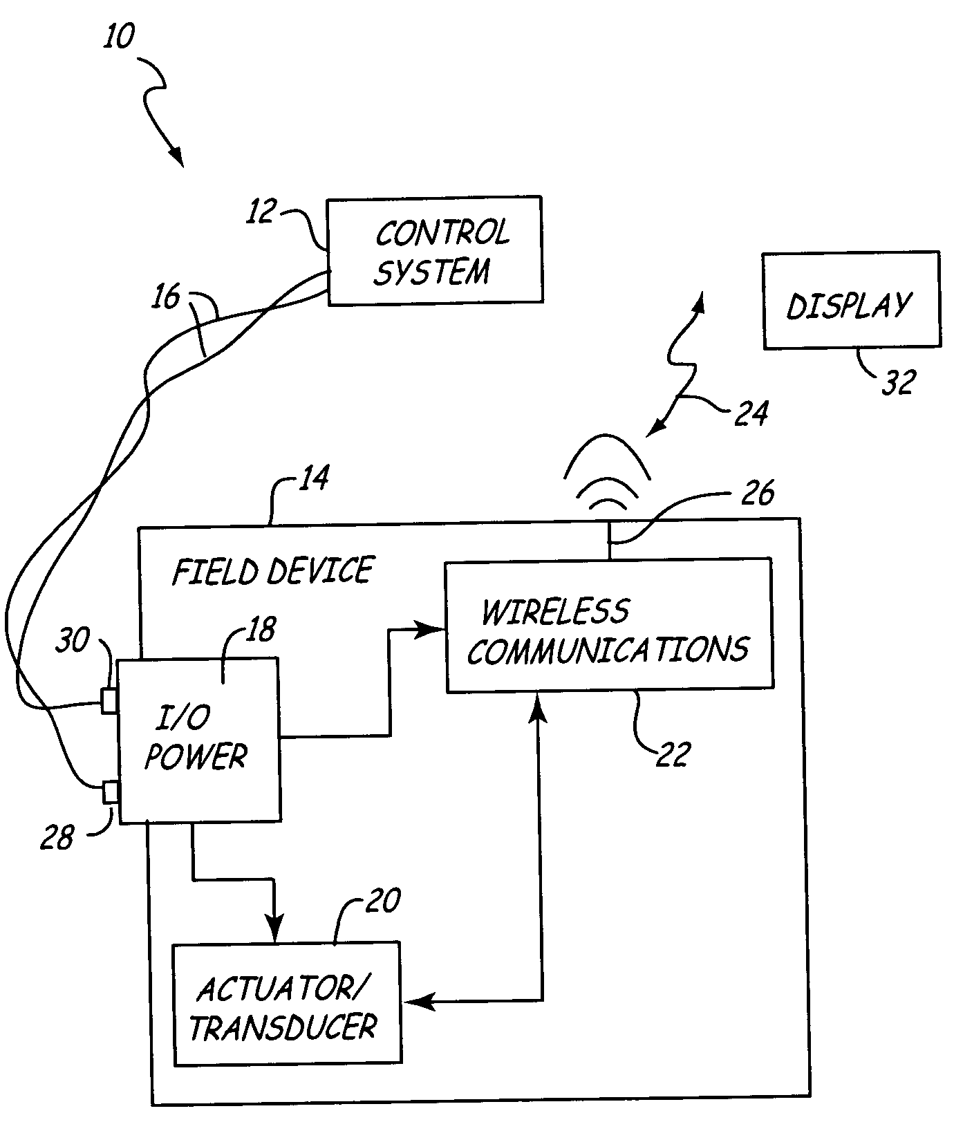
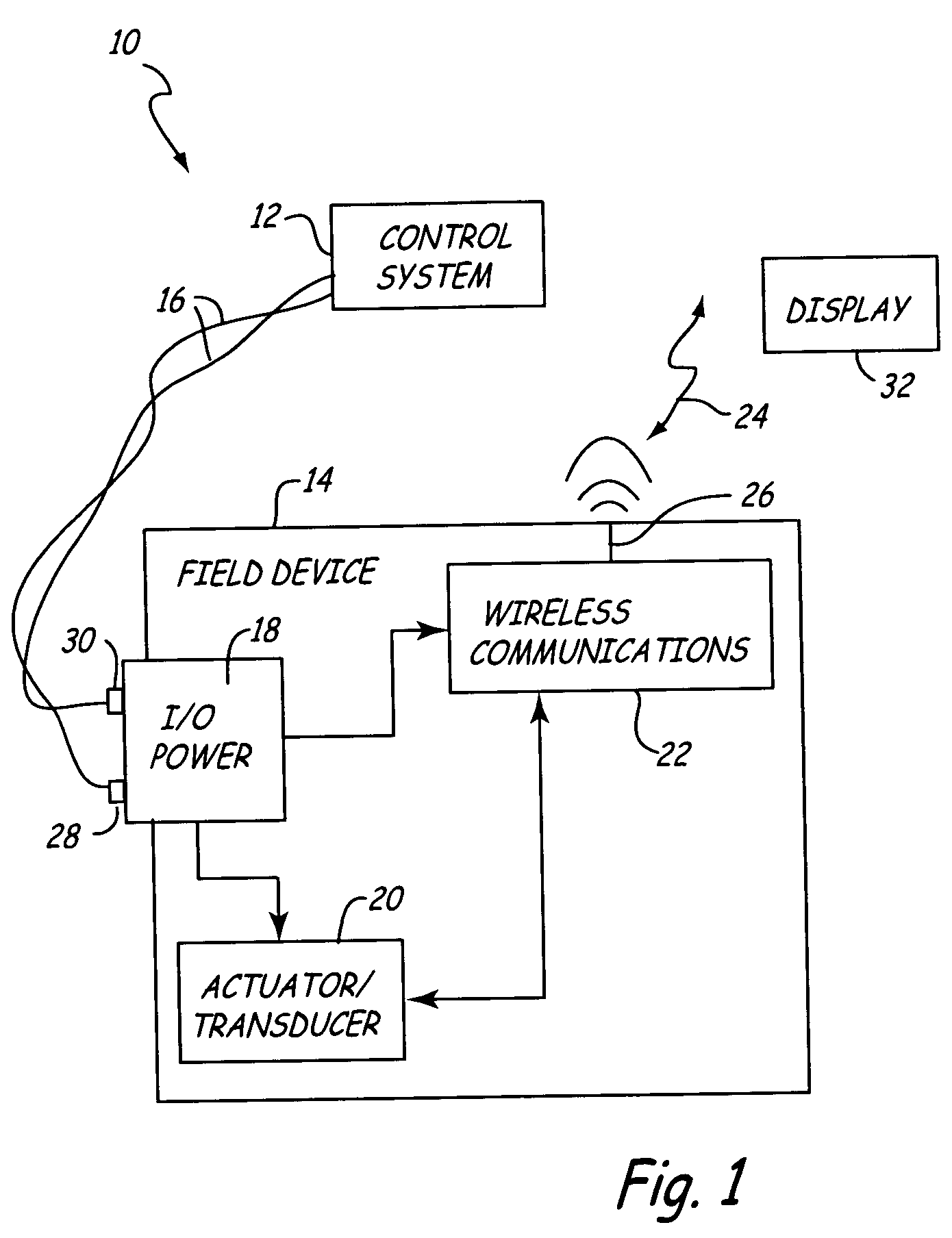
[0016]FIG. 1 is a simplified block diagram of a process control or monitoring system 10 in which a control room or control system 12 couples to a field device 14 over a two-wire process control loop 16. The field device 14 includes I / O power circuitry 18, actuator / transducer 20 and wireless communication circuitry 22. The wireless communication...


PUM


Abstract

A field device for use in an industrial process control or monitoring system includes terminals configured to connect to a two-wire process control loop. The loop carries data and provides power to the field device. RF circuitry in the field device is provided for radio frequency communication. A power supply powers the RF circuitry using power received from the two-wire process control loop.

Description

BACKGROUND OF THE INVENTION[0001]The present invention relates to industrial process control or monitoring systems. More specifically, the present invention relates to field devices in such systems which are capable of Radio Frequency (RF) communication.[0002]In industrial settings, control systems are used to monitor and control inventories of industrial and chemical processes, and the like. Typically, the control system performs these functions using field devices distributed at key locations in the industrial process and coupled to the control circuitry in the control room by a process control loop. The term “field device” refers to any device that performs a function in a distributed control or process monitoring system, including all devices currently known, or yet to be known, used in the measurement, control and monitoring of industrial processes.[0003]Some field devices include a transducer. A transducer is understood to mean either a device that generates an output signal b...

Claims


Application Information

Patent Timeline
Patent Type & Authority Patents(United States)
IPC IPC(8): G08B29/00G05B19/418G06F13/14
CPCG05B19/4185G05B2219/33192Y02P90/02Y02P90/80
Inventor KARSCHNIA, ROBERT J.WILLCOX, CHARLES R.BRODEN, DAVID A.WESTFIELD, BRIAN L.ORTH, KELLY M.
Owner ROSEMOUNT INC
Learn More