
Small planar antenna with enhanced bandwidth and small rectenna for RFID and wireless sensor transponder

a technology of wireless sensor and small planar antenna, which is applied in the direction of slot antenna, antenna, instruments, etc., can solve the problems of antenna miniaturization technology, affecting the operation frequency bandwidth, and requiring the compromise between the size, bandwidth and efficiency of the antenna and the antenna as described, so as to achieve the effect of enhancing the operating frequency bandwidth

Inactive Publication Date: 2007-08-28
SAMSUNG ELECTRONICS CO LTD
View PDF8 Cites 31 Cited by
  • Summary
  • Abstract
  • Description
  • Claims
  • Application Information

AI Technical Summary

Benefits of technology

The design achieves a 30% wider operating bandwidth compared to conventional antennas without compromising radiation pattern, efficiency, or polarization purity, and provides a cost-effective solution by eliminating the need for external matching circuits, with improved RCS for enhanced data transmission in RFID systems.

Problems solved by technology

Of course, antenna can be smaller, but at expense of bandwidth, gain, and efficiency.
That is, the antenna miniaturization technology requires the compromise among the size, bandwidth and efficiency of the antenna.
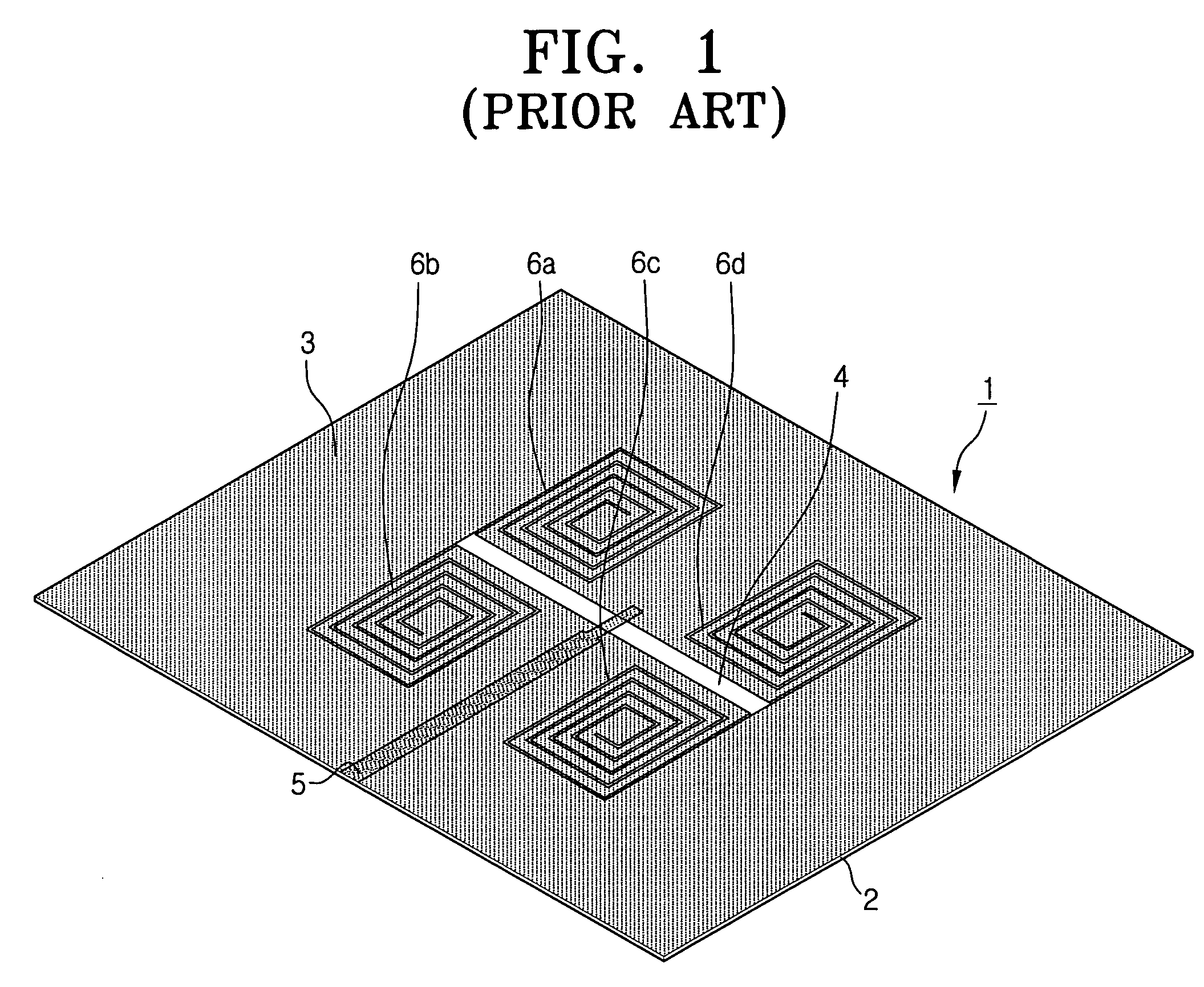
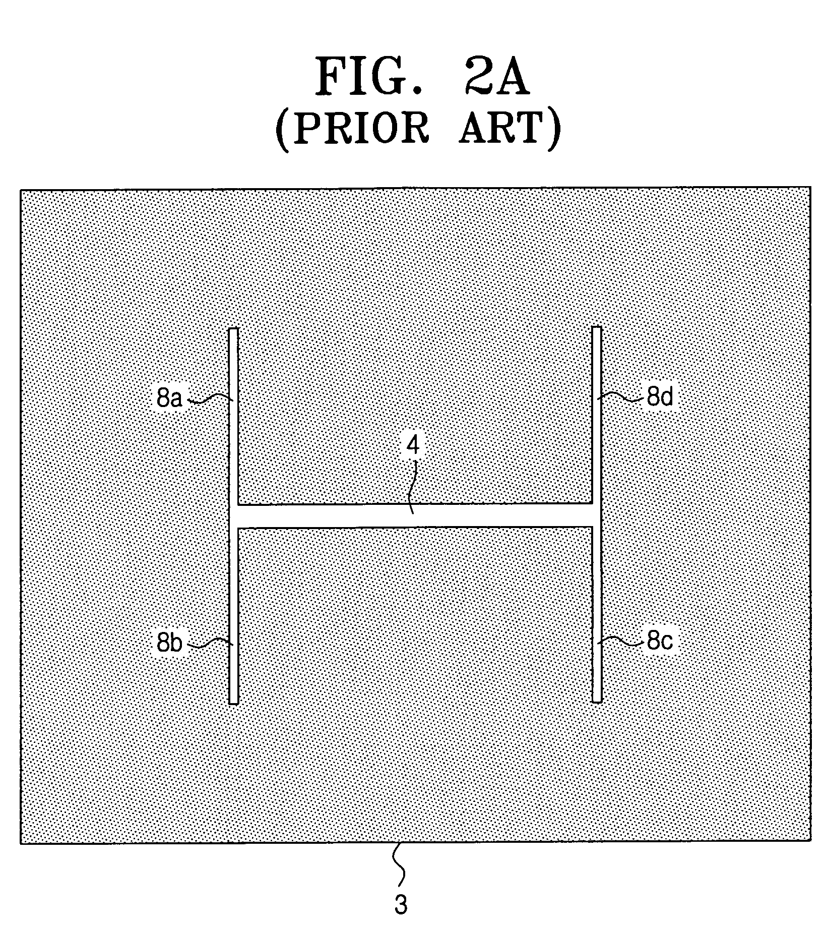
The conventional antennas as described above, however, have the drawback in that their bandwidths are generally narrow.
In diverse application fields, the small operating frequency bandwidth of a small antenna causes serious problems.
However, the implementation of the small antenna in the RFID and / or wireless sensor transponder design causes another problem in that the semiconductor chip of the transponder essentially has a complex input impedance having a capacitive reactance.
Due to specified safety regulations and other legislations, the power radiated from the interrogator is somewhat limited.
However, this conventional method has a new problem in that its manufacturing cost is ridiculously increased.
Additionally, this separation type matching circuit greatly reduces the performance of the system.

Method used


Image

  • Small planar antenna with enhanced bandwidth and small rectenna for RFID and wireless sensor transponder
  • Small planar antenna with enhanced bandwidth and small rectenna for RFID and wireless sensor transponder
  • Small planar antenna with enhanced bandwidth and small rectenna for RFID and wireless sensor transponder

Examples


Embodiment Construction

[0071]Certain exemplary embodiments of the present invention will be described in greater detail with reference to the accompanying drawings.

[0072]In the following description, same drawing reference numerals are used for the same elements even in different drawings. The matters defined in the description such as a detailed construction and elements are nothing but the ones provided to assist in a comprehensive understanding of the invention. Thus, it is apparent that the present invention can be carried out without those defined matters. Also, well-known functions or constructions are not described in detail since they would obscure the invention in unnecessary detail.

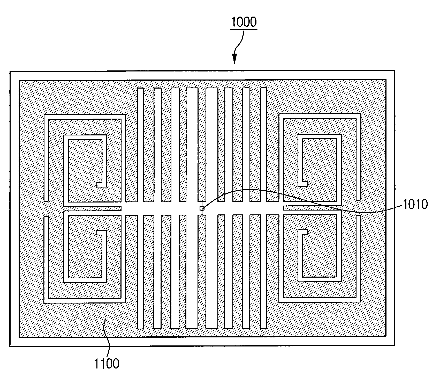
[0073]FIG. 4 is a perspective view of a small planar antenna according to an exemplary embodiment of the present invention. Referring to FIG. 4, the small planar antenna 100 comprises a dielectric substrate 20, a metal layer 30 formed on an upper part of the dielectric substrate 20, a main slot 40 and a plurality of s...


PUM


Abstract

A small planar antenna with an enhanced bandwidth and a small rectenna for RFID (Radio Frequency Identification) and wireless sensor transponder are provided. The small planar antenna includes a dielectric substrate, a metal layer formed on an upper part of the dielectric substrate, a main slot formed in pattern on the metal layer, and a plurality of sub-slots connected to the main slot and winding in a specified direction, and the plurality of sub-slots form a pair of symmetric sub-slot groups around the main slot. According to the small planar antenna, the antenna region that substantially takes part in the radiation is substantially increased, and thus an enhanced bandwidth can be obtained without affecting the radiation pattern, radiation efficiency, polarization purity, etc., of the antenna.

Description

[0001]This application claims benefit under 35 U.S.C. § 119 from Korean Patent Application No. 2005-26496, filed on Mar. 30, 2005, and from Korean Patent Application No. 2004-66159, filed on Aug. 21, 2004, in the Korean Intellectual Property Office, the disclosures of which are incorporated herein by reference.BACKGROUND OF THE INVENTION[0002]1. Field of the Invention[0003]The present invention relates to a RF antenna and a microwave antenna, and more particularly to an electrically small planar antenna matched with an electronic chip of RFID (Radio Frequency Identification) and / or a wireless sensor transponder.[0004]2. Description of the Related Art[0005]At UHF-frequencies and in the L-band the size of even a single-half-wave dipole antenna is precluded in many mobile and Radio Frequency-Identification (RFID) applications. So small (relative to wavelength) antennas are in very high demand. However, the size of the antenna for a given application is not related mainly to the techno...

Claims


Application Information

Patent Timeline
Patent Type & Authority Patents(United States)
IPC IPC(8): H01Q13/10G06K19/07G06K19/077
CPCH01Q1/248H01Q1/38H01Q5/371H01Q5/28H01Q13/10
Inventor TIKHOV, YURIMIN, YOUNG-HOONKIM, YONG-JIN
Owner SAMSUNG ELECTRONICS CO LTD
Learn More