
Ion optical mounting assemblies

a technology of optical mounting and assembly, which is applied in the field of ion optical mounting assemblies, can solve the problems of reducing the resolution and sensitivity of other operational modes, difficult tasks, and difficult to achieve accurate results, and achieve the effects of improving the dynamic mass range, increasing resolution, and improving accuracy

Inactive Publication Date: 2007-09-04
APPL BIOSYSTEMS INC +1
View PDF2 Cites 17 Cited by
  • Summary
  • Abstract
  • Description
  • Claims
  • Application Information

AI Technical Summary

Benefits of technology

[0001]The development of matrix-assisted laser desorption / ionization (“MALDI”) techniques has greatly increased the range of biomolecules that can be studied with mass analyzers. MALDI techniques allow normally nonvolatile molecules to be ionized to produce intact molecular ions in a gas phase that are suitable for analysis. One class of MALDI instrument, which have found particular use in the study of biomolecules, are MALDI tandem time-of-flight mass spectrometers, referred to as MALDI-TOF MS / MS instruments hereafter.

Problems solved by technology

In practice, however, achieving accurate results is not easy, and the greater the accuracy required in the analysis, the more difficult the task.
Although instruments exist where the mode of operation can be switched, the instrument configurations and operational conditions that provide good resolution and sensitivity for one mode of operation (e.g., linear TOF, reflectron TOF, and MS / MS TOF) can significantly decrease the resolution and sensitivity for other operational modes.
In addition, in many biological studies there is a limited amount of sample available for study (such as, e.g., rare proteins, forensic samples, archeological samples).
In general, it is simple to optimize an ion optical system for a single collision energy that provides good focusing into the second TOF region following the collision cell, however, it is considerably more difficult to provide an ion optical system that provides good focusing into the second TOF region across a range of collision energies, without compromising ion transmission efficiency and thereby instrument sensitivity.
MALDI-TOF MS / MS instruments can also be very complex machines requiring the accurate alignment and interaction of myriad components for useful operation.
Misalignment of theses and non-uniformity in their electrical fields can significantly degrade the performance of a mass spectrometry instrument.
Once positioned, subsequent movements of the ion optical elements can significantly degrade instrument performance.
For example, if an element moves out of alignment after an instrument has been tuned, the instrument's mass accuracy, sensitivity and resolution can be adversely affected.
In addition, such traditional methods of assembly often require the assembler to tighten the bolts in both a specific pattern and with specific torques to properly align the ion optical elements, e.g. without warping.
Such procedures, however, can be time-consuming and can require a skilled assembler to perform.
In addition, as the alignment tolerances of instruments decrease (e.g., to improve sensitivity, decrease instrument size, etc.) misalignment errors become less and less noticeable to the naked eye and harder to detect by the less skilled assembler.
However, it is more difficult to design a singular geometry that provides optimized performance in more than one mode of operation without sacrificing performance elsewhere.
In particular, to optimize the source for a focal plane close to the source, such as can be required for timed ion selection for MS / MS, the spatial focusing of the beam (in x, y) is degraded to the point where significant portions of the ion beam are not transmitted through critical apertures; and hence, a substantial loss of instrument sensitivity is observed.

Method used


Image

  • Ion optical mounting assemblies
  • Ion optical mounting assemblies
  • Ion optical mounting assemblies

Examples


Embodiment Construction

[0085]In various aspects, the present teachings provide novel MALDI-TOF systems. In various embodiments, provided are novel MALDI-TOF systems comprising one or more novel components such as, for example, sample support handling mechanisms, ion sources, ion optics and ion optical assemblies. In various embodiments, provided are novel methods for use with a mass spectrometry system to, for example, provide sample ions, focus sample ions, operate a mass spectrometry system in different operational modes, and operate ion fragmentors.

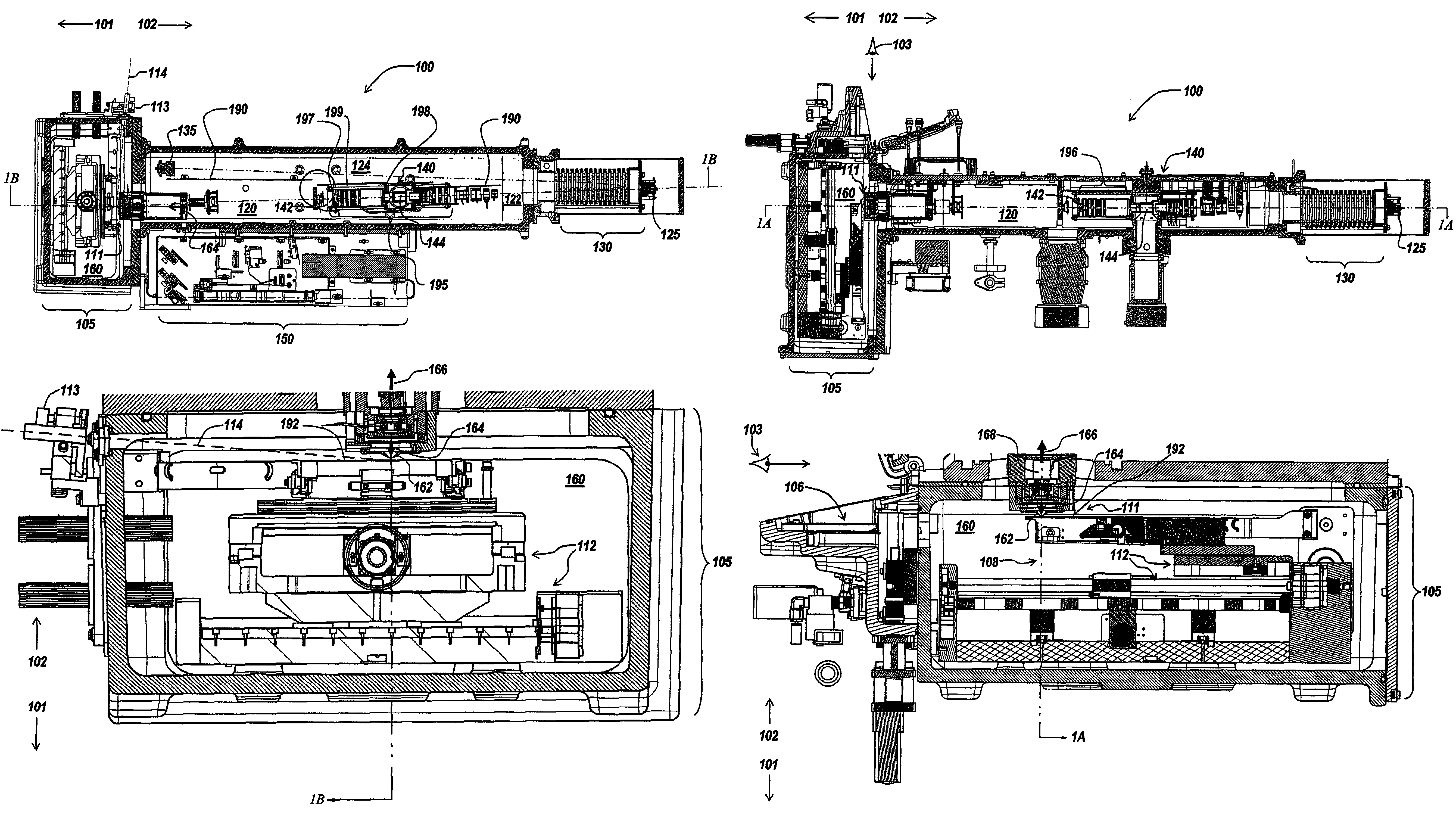
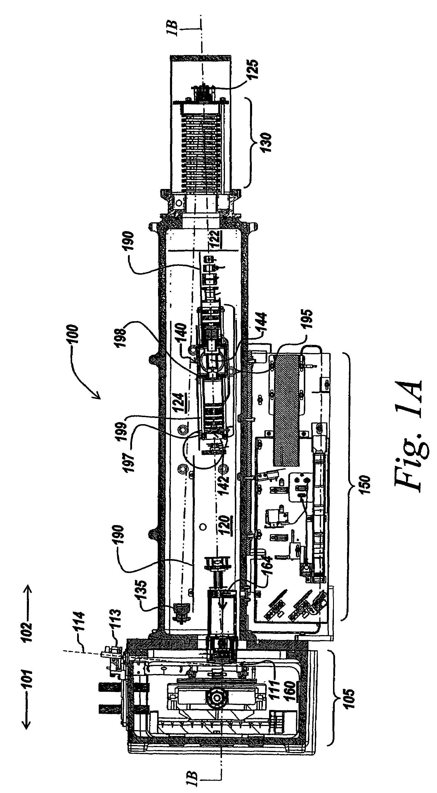
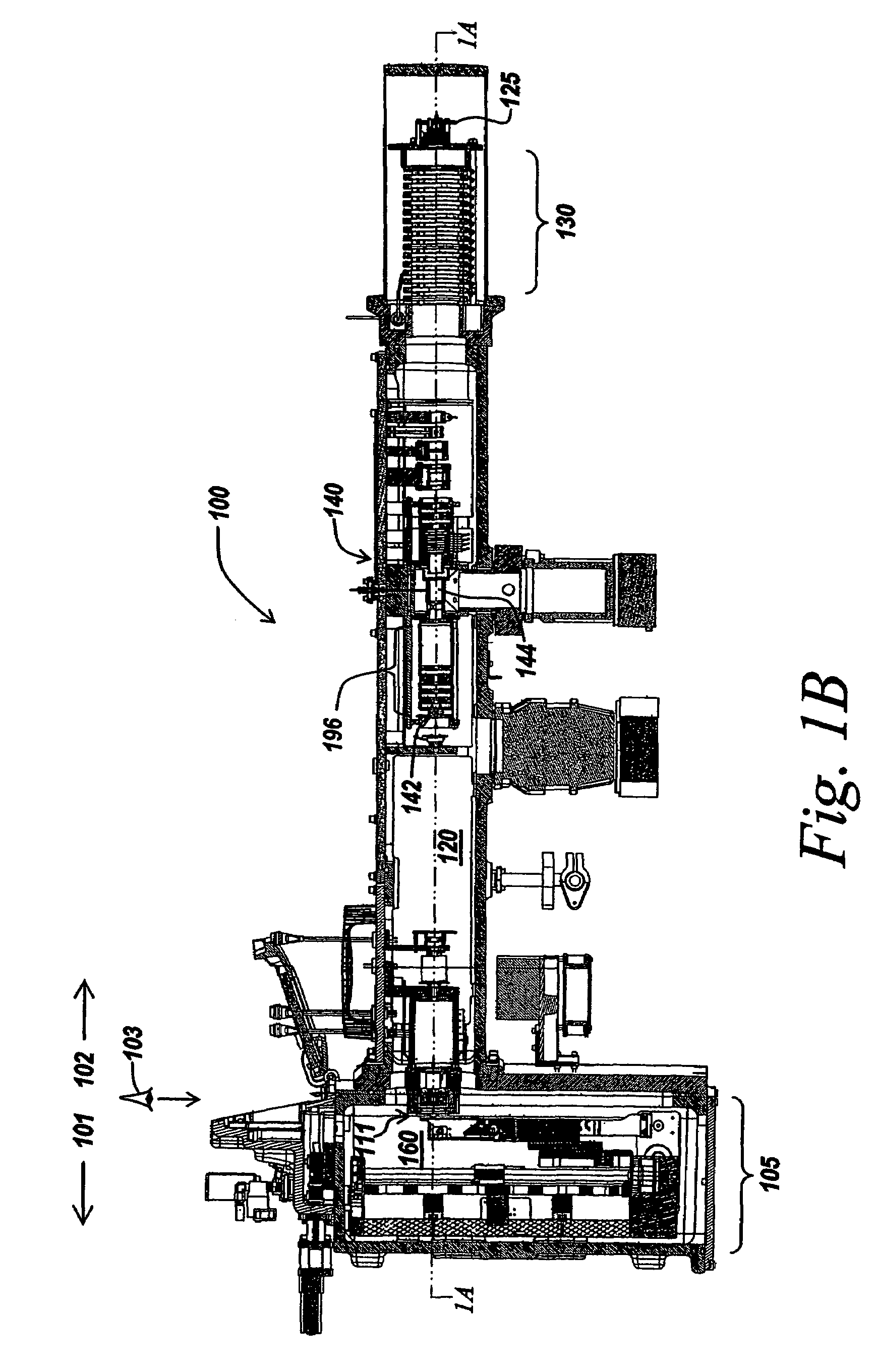
[0086]FIGS. 1A-1D depict substantially to scale views of a MALDI-TOF system 100 in accordance with various embodiments of the present teachings. FIG. 1A depicting a front sectional view, FIG. 1B a side sectional view, and FIGS. 1C and 1D presenting expanded views of portions of FIGS. 1A and 1B, respectively. To facilitate the viewing of FIGS. 1A-1D, the system 100 can be oriented such that the floor is in direction 101, the ceiling in direction 102, and the ...


PUM

PropertyMeasurementUnit
pressureaaaaaaaaaa
pressureaaaaaaaaaa
angleaaaaaaaaaa

Abstract

In various embodiments, provided are ion optical assemblies, and systems for mounting and aligning ion optic components. In various embodiments, the present teachings provide ion optical assemblies with features that facilitate the alignment of ion optical elements. In various embodiments, the alignment of the ion optical elements by compressing them with securing members, as described in the present teachings, can simplify the alignment and assembly of ion optical elements. In the present teachings, no torque pattern is required to compress and align the ion optical elements. In various embodiments, the present teachings provide systems for mounting and aligning ion optic components that facilitate their alignment.

Description

INTRODUCTION[0001]The development of matrix-assisted laser desorption / ionization (“MALDI”) techniques has greatly increased the range of biomolecules that can be studied with mass analyzers. MALDI techniques allow normally nonvolatile molecules to be ionized to produce intact molecular ions in a gas phase that are suitable for analysis. One class of MALDI instrument, which have found particular use in the study of biomolecules, are MALDI tandem time-of-flight mass spectrometers, referred to as MALDI-TOF MS / MS instruments hereafter.[0002]A traditional tandem mass spectrometer (MS / MS) instrument uses multiple mass separators in series. An MS / MS instrument can be use, for example, to determine structural information, such as, e.g., the sequence of a protein. Traditional MS / MS techniques use the first mass separator (often referred to as the first dimension of mass spectrometry) to transmit molecular ions in a selected mass-to-charge (m / z) range (often referred to as “the parent ions” o...

Claims


Application Information

Patent Timeline
Patent Type & Authority Patents(United States)
IPC IPC(8): A61N5/00G21G5/00
CPCH01J49/06Y10T409/30868
Inventor MARTIN, III, ROY E.
Owner APPL BIOSYSTEMS INC
Learn More