
Display apparatus and display apparatus drive method

Inactive Publication Date: 2007-09-04
PANASONIC CORP
View PDF18 Cites 14 Cited by
  • Summary
  • Abstract
  • Description
  • Claims
  • Application Information

AI Technical Summary

Benefits of technology

[0009]An object of this invention is the provision of a display device and a driving method for the display device which enables improvement of edge blur, while also enabling suppression of the decrease in brightness.

Problems solved by technology

Because these liquid crystal display devices are hold-type display devices in which display of an image is continued for one frame interval, there is occurrence of motion blurring phenomena (hereafter called “edge blur”), in which the outlines of images are blurred during video display, and so video display performance comparable to that of the CRTs (cathode-ray tubes) generally used in television sets is not obtained.
The longer the black display interval is made in order to improve edge blur, the more pronounced is this tendency, so that brightness is decreased and satisfactory video display is not possible.
Hence when a black display interval appropriate to an image having an average motion amount is set, edge blur can be reduced sufficiently for images with a small amount of motion, but the brightness is reduced unnecessarily, and satisfactory video display is not possible.
Further, when using a TN (Twisted Nematic) mode in the above-described liquid crystal display device, the driving response time is slow at approximately 16 ms, so that even if a black display interval is set, edge blur may remain due to the slowness of the driving response of the liquid crystal panel.

Method used


Image

  • Display apparatus and display apparatus drive method
  • Display apparatus and display apparatus drive method
  • Display apparatus and display apparatus drive method

Examples


Embodiment Construction

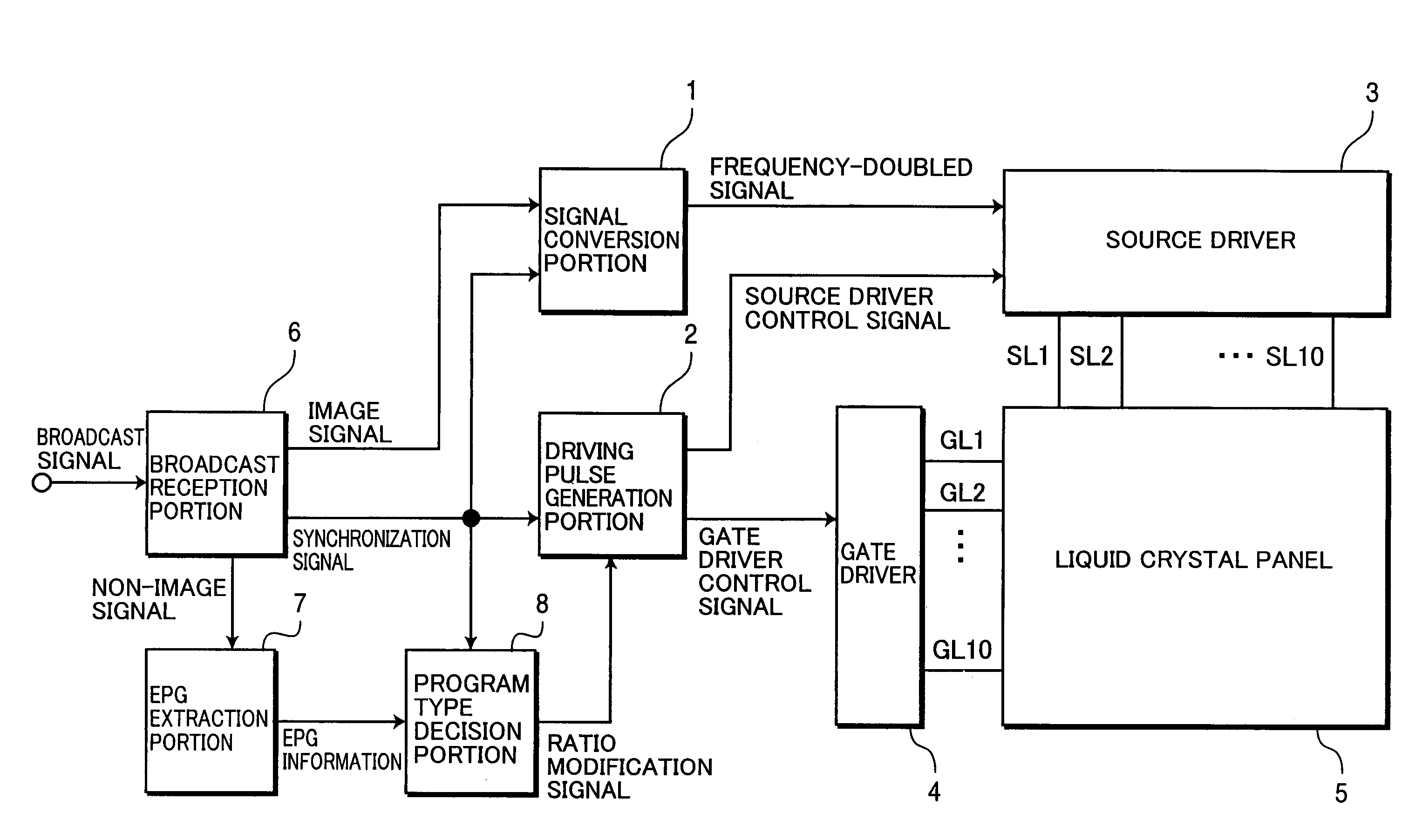
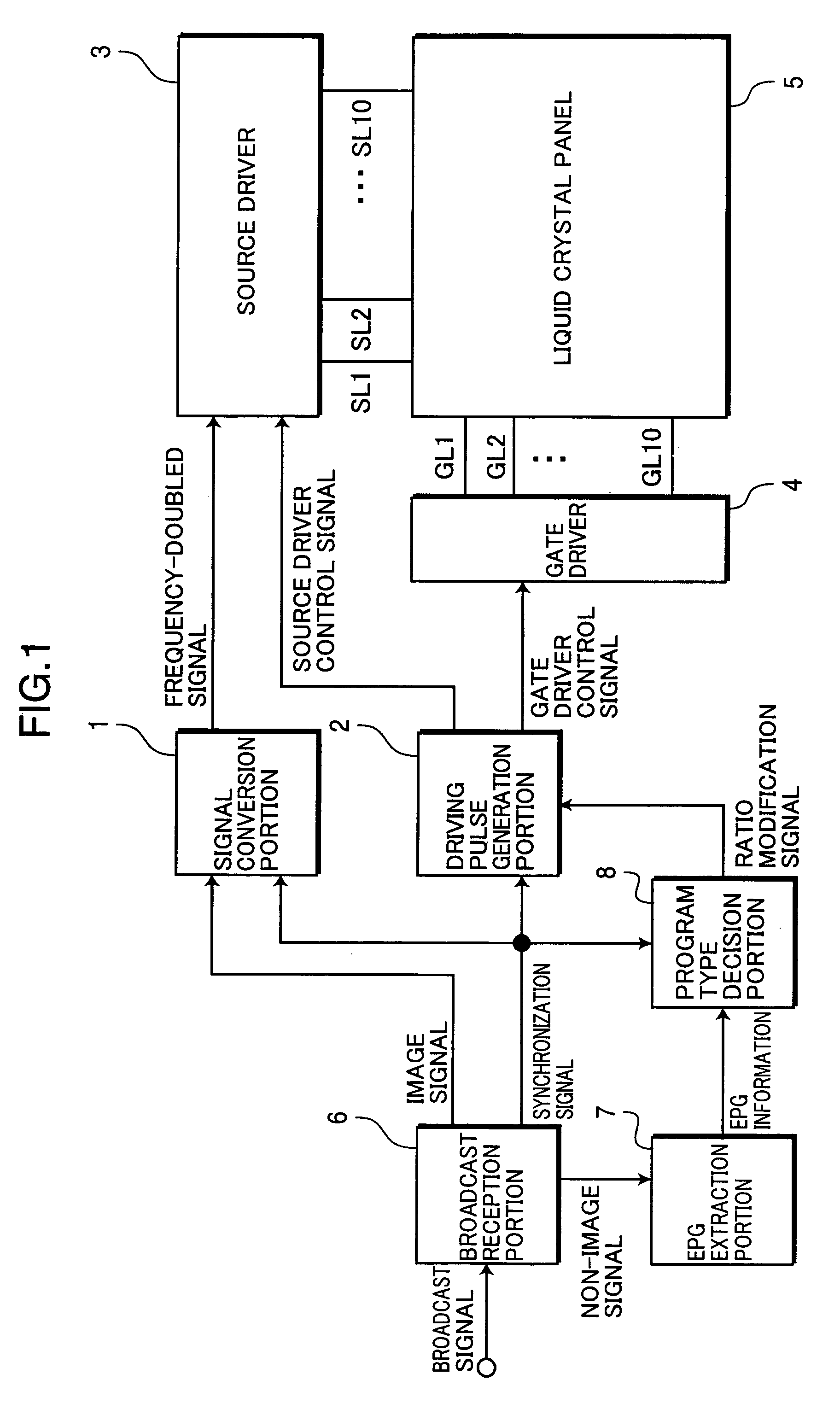
[0040]Below, display devices of different aspects of the invention are explained, referring to the drawings. FIG. 1 is a block diagram showing the configuration of the display device of a first aspect of the invention. In FIG. 1, to simplify the drawing, the number of source lines and the number of gate lines are each shown to be 10, but the number of source lines and the number of gate lines are not limited to this number, and can be changed variously.

[0041]The liquid crystal display device shown in FIG. 1 comprises a signal conversion portion 1, driving pulse generation portion 2, source driver 3, gate driver 4, liquid crystal panel 5, broadcast reception portion 6, EPG (electronic program guide) extraction portion 7, and program type decision portion 8.

[0042]The broadcast reception portion 6 receives broadcast signals and separates the broadcast signals into image signals, synchronization signals, and non-image signals, and outputs the image signals and synchronization signals to...


PUM


Abstract

An EPG extraction portion extracts EPG information; a program type decision portion decides the type of broadcast program using the extracted EPG information, and outputs a ratio modification signal to change the ratio of the image display interval to the black display interval according to the program type; a driving pulse generation portion generates a gate driver control signal which changes the write timing of a frequency-doubled image signal and frequency-doubled black display signal in one field interval, according to the ratio modification signal; and, a gate driver changes the write timing of the frequency-doubled image signal and frequency-doubled black display signal according to the gate driver control signal, to change the ratio of the image display interval to the black display interval.

Description

TECHNICAL FIELD[0001]This invention relates to a hold-type display device which continues display of an image for a prescribed display interval, and a driving method for such a display device.BACKGROUND ART[0002]Conventionally, liquid crystal display devices have frequently been used as computer display devices by virtue of their light weight, thin shape, low power consumption, and other advantages, but as screen sizes have grown, there has been a gradual increase in the cases of use as television sets. Because these liquid crystal display devices are hold-type display devices in which display of an image is continued for one frame interval, there is occurrence of motion blurring phenomena (hereafter called “edge blur”), in which the outlines of images are blurred during video display, and so video display performance comparable to that of the CRTs (cathode-ray tubes) generally used in television sets is not obtained.[0003]Numerous research reports have been published concerning the...

Claims


Application Information

Patent Timeline
IPC IPC(8): G09G3/36G02F1/133G09G3/20G09G3/34H04N5/445H04N5/66H04N7/025H04N7/03H04N7/035H04N7/08H04N7/088
CPCG09G3/3406G09G3/3648H04N5/66H04N7/08H04N7/0887G09G2310/02G09G2310/0251G09G2310/061G09G2320/0261G09G2320/06G09G2320/0606G09G2320/0613G09G2320/062G09G2320/0633G09G2320/064G09G2320/10G09G2330/021H04N21/482G09G3/36
Inventor KUMAMOTO, YASUHIROFUNAMOTO, TARO
Owner PANASONIC CORP
Learn More