Wall block mold

a wall block and mold technology, applied in the field of masonry blocks, can solve the problems of inability to produce a block with a roughened facing that is bowed or curved, adds to the time and cost of the finished product, and is relatively small

Active Publication Date: 2007-09-11
MORRELL KELLY J
View PDF33 Cites 48 Cited by
  • Summary
  • Abstract
  • Description
  • Claims
  • Application Information

AI Technical Summary

Benefits of technology

[0022]An advantage of the invention is that the block may be used to construct substantially vertical walls, walls having a slope or batter, walls comprising a combination of vertical and sloping portions, or serpentine walls.
[0023]Another advantage of the invention is that the block may be interlocked with blocks in adjacent courses of blocks without modifications or adaptors.

Problems solved by technology

A drawback with the afore-mentioned manufacturing techniques is that they are unable to produce a block that has a roughened facing that is bowed or curved with respect to the extrusion or stripping direction.
As one may imagine, each additional processing step adds to the time and cost of the finished product.
A drawback with the afore-mentioned dry cast blocks is that that they are relatively small.
Often, it is necessary to provide stabilization devices for each course of blocks or for every other course of blocks, which adds to the cost of materials, labor, and time of construction.
Unfortunately, stabilization devices can stretch, break, or be pulled out from the wall structure, which can lead to premature wall failure.
Another drawback common to most dry cast blocks is that they usually have only one facing or exposed face area.
Thus, they are limited to a particular orientation within a structure.
This limitation is underscored when the blocks are trapezoidal in shape, for example.
Another drawback common to most dry cast blocks is that they are designed and configured to engage vertically adjacent blocks in certain, predetermined arrangements.

Method used


Image

  • Wall block mold
  • Wall block mold
  • Wall block mold

Examples


Embodiment Construction

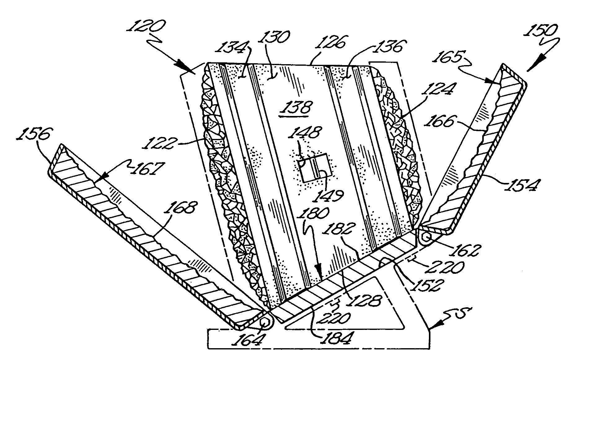
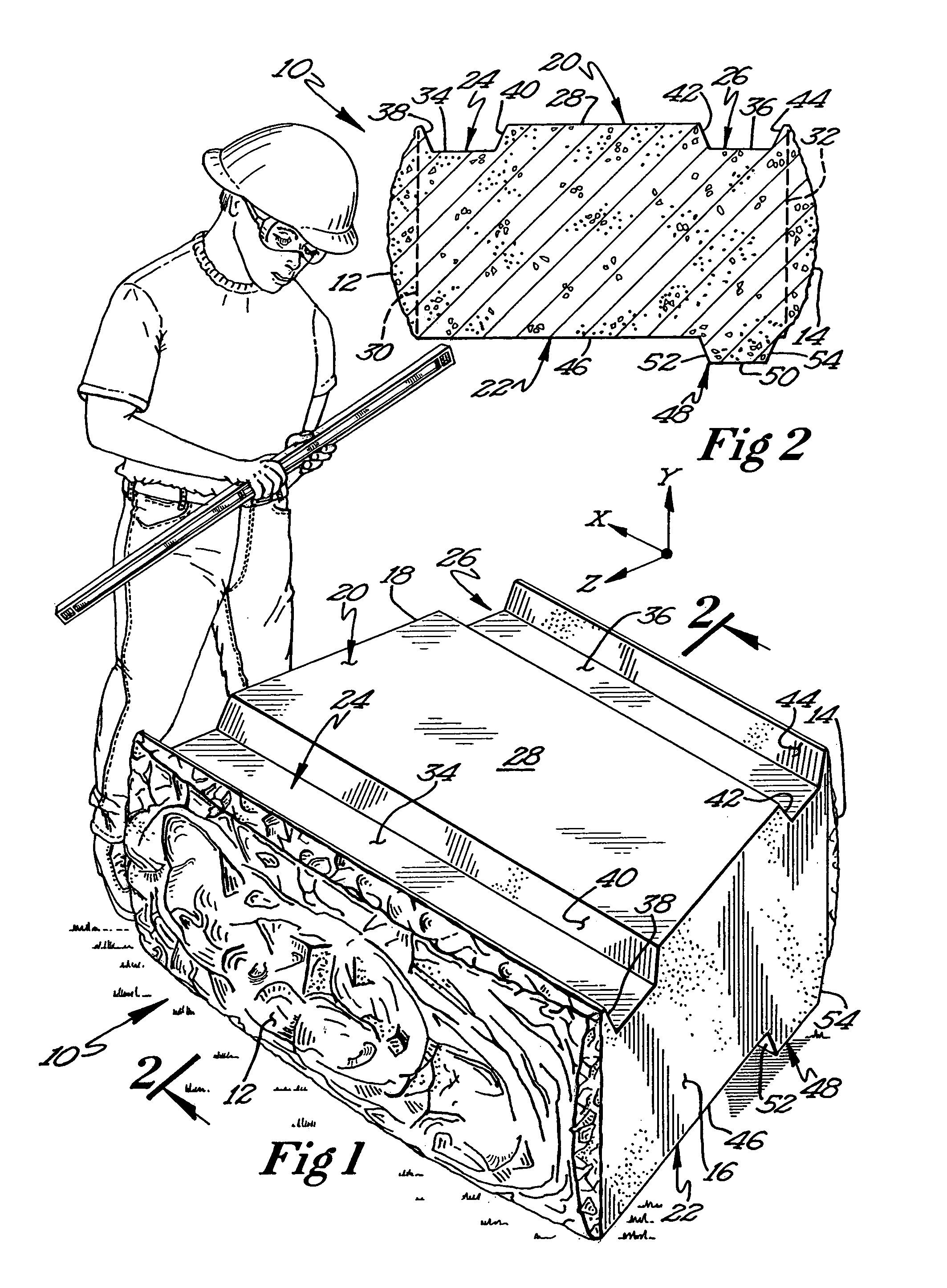
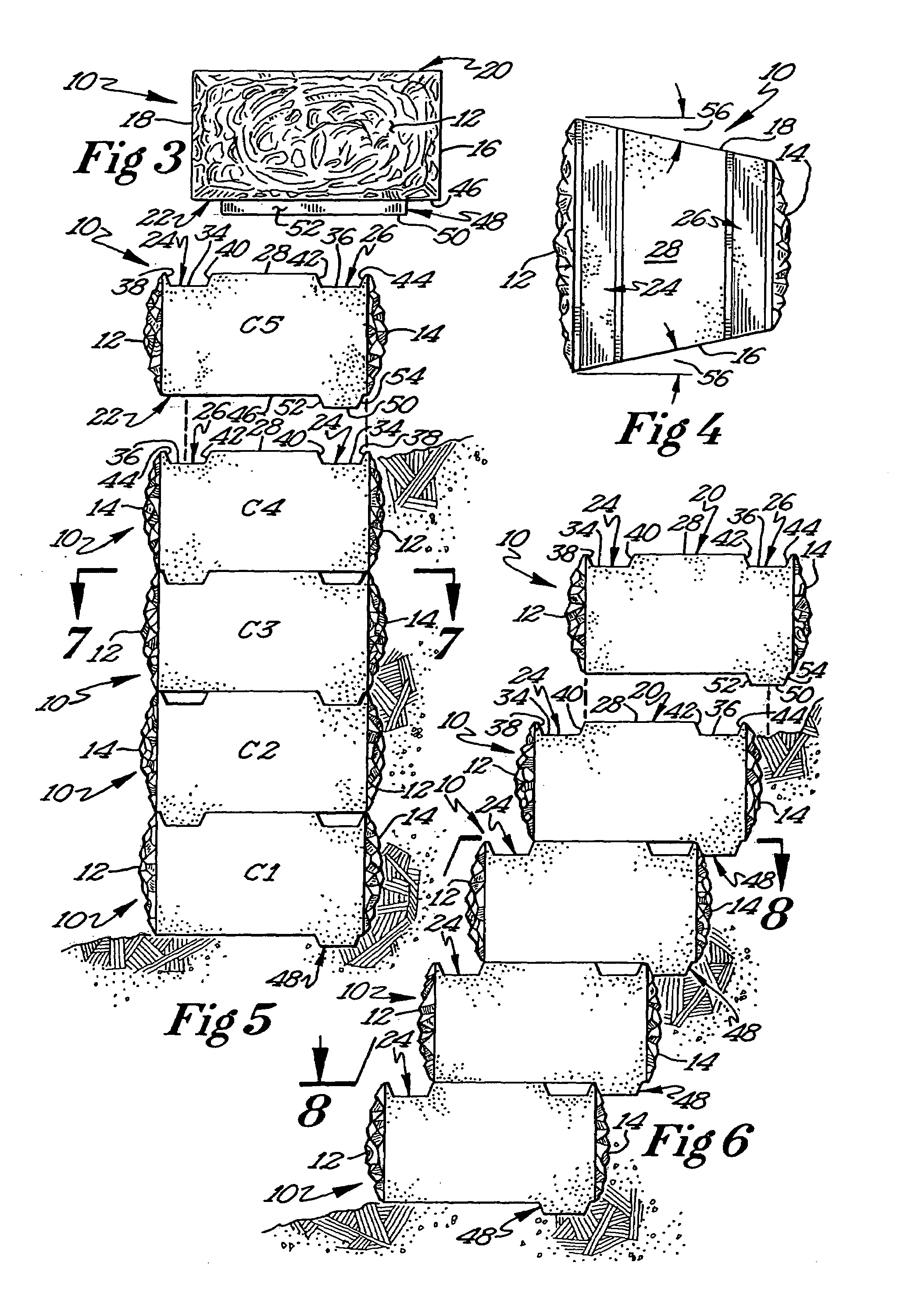
[0052]A preferred embodiment of a block of the present invention is depicted in FIG. 1. As can be seen, the block 10 is generally trapezoidally shaped and includes a front surface 12, a rear surface 14, a pair of opposed side surfaces 16 and 18 that extend between the front 12 and rear 14 surfaces, a top surface 20, and a bottom surface 22. The front surface 12, as shown, is rough textured and substantially non-planar, and extends outwardly with respect to the front edges of the top, bottom, and opposed side surfaces. Preferably, the maximum extent or relief of the outward extension is in the range of about 2.5 to 33.3 percent of the height of the block, taken in the y direction in a three-dimensional coordinate system. The rear surface 14 is similarly textured (see, for example, FIGS. 2, 4, and 7-12) and also extends outwardly with respect to the rear edges of the top, bottom, and opposed side surfaces. As with the front surface 12, the maximum outward extent or relief of the rear ...


PUM

PropertyMeasurementUnit
volumesaaaaaaaaaa
areaaaaaaaaaaa
depthaaaaaaaaaa

Abstract

A system and method of forming differently sized and / or textured construction blocks from a single mold. The system includes a mold having a base and movable side walls that cooperate with the base to form a mold cavity, and one or more inserts that are configured to be positioned in the mold. The mold is arranged and oriented so that its side walls form the top, bottom, front, and rear surfaces of each block. The inserts may be used individually or grouped together into predetermined sets to form different blocks, such as interior and end blocks, as well as cap stones.

Description

CROSS REFERENCE TO PRIOR APPLICATION[0001]This is a continuation-in-part of application Ser. No. 10 / 437,565, filed May 14, 2003.FIELD OF THE INVENTION[0002]The present invention generally relates to masonry blocks. More particularly, the present invention relates to mortarless masonry blocks that may be used to construct vertical freestanding walls or sloping walls.BACKGROUND OF INVENTION[0003]Mortarless masonry blocks have been known and used for many years. They are quite popular because they do not require extensive site preparation or the services of skilled craftsmen, and they are aesthetically pleasing, invoking feelings of stability, durability, and permanence. Besides being attractive and sturdy, they are generally small enough to be able to be lifted and manipulated by one person. They can range from about 6-120 pounds but more typically, though, they range around 35-70 pounds. In addition, they characteristically have only one facing or exposed face with an area in the ran...

Claims


Application Information

Patent Timeline
Patent Type & Authority Patents(United States)
IPC IPC(8): B29C70/00B28B11/08
CPCB28B7/0044B28B7/007B28B7/0082E04C1/395E04B2002/0208E04B2002/0263E04B2002/0269
Inventor MORRELL, KELLY J.
Owner MORRELL KELLY J
Why Eureka
Try Eureka