Steep angle cutter hub with blunt edge blades

a technology of cutter hubs and blades, which is applied in the direction of dough shaping, manufacturing tools, food shaping, etc., can solve the problems of failure to provide a cutter hub and blade assembly, and achieve the effect of reducing the formation of fines and ensuring grind

Inactive Publication Date: 2007-09-11
GALA INDUSTRIES INC
View PDF9 Cites 23 Cited by
  • Summary
  • Abstract
  • Description
  • Claims
  • Application Information

AI Technical Summary

Benefits of technology

[0011]The blunt edge blades of the present invention are easier and quicker to grind and seat to the die face because the bottom surface contact area can be adjusted and reduced as desired for the extrudate being pelletized. Further, the narrow tip edge second blade embodiment of the present invention provides for more rapid seating of new blades to the face of the die plate since only a very small area of the cutting edge or tip end of the cutting blade initially engages the die face.
[0022]A final object of the present invention to be set forth herein is to provide a cutter hub and blade assembly for underwater pelletizers in accordance with the preceding objects, which can be easily manufactured from readily available and known components for ease and economy of manufacture and which will be sturdy and long lasting in operation and use.

Problems solved by technology

These prior art structures, however, fail to provide a cutter hub and blade assembly for a pelletizer in which the cutter blades have a bottom surface contact area that can be adjusted and reduced regardless of blade thickness, that can provide a blunt or generally perpendicular leading edge to shear the extruding strands into pellets, that can be used on existing cutter hubs, and that can more readily seat against the die face, especially already used and slightly worn die faces.

Method used


Image

  • Steep angle cutter hub with blunt edge blades
  • Steep angle cutter hub with blunt edge blades
  • Steep angle cutter hub with blunt edge blades

Examples


Embodiment Construction

[0040]The foregoing description and drawings should be considered as illustrative only of the principles of the invention. Numerous applications of the present invention will readily occur to those skilled in the art. Therefore, it is not desired to limit the invention to the preferred embodiment or the exact construction and operation of the preferred embodiment shown and described. Rather, all suitable modifications and equivalents may be resorted to, falling within the scope of the invention.

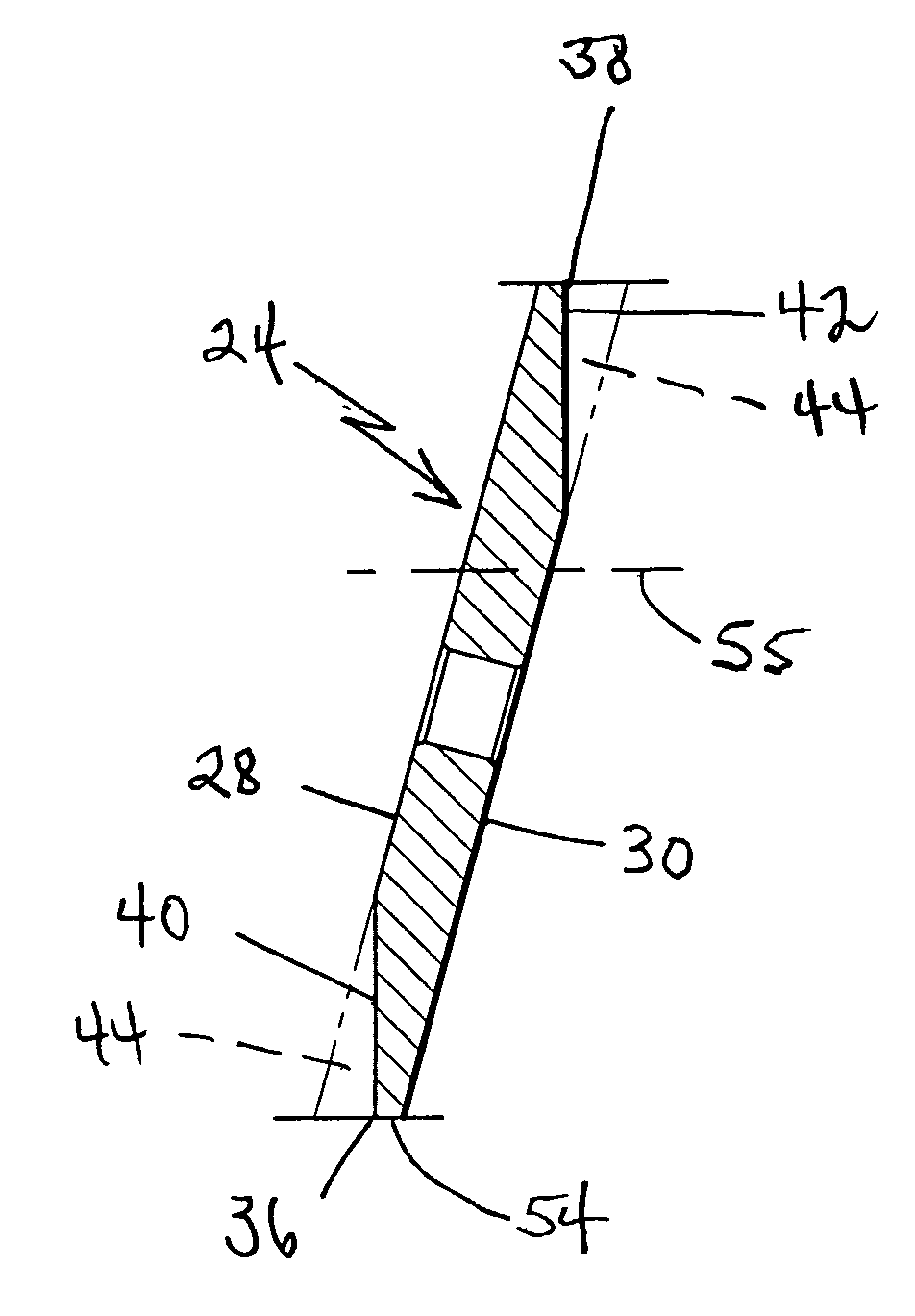
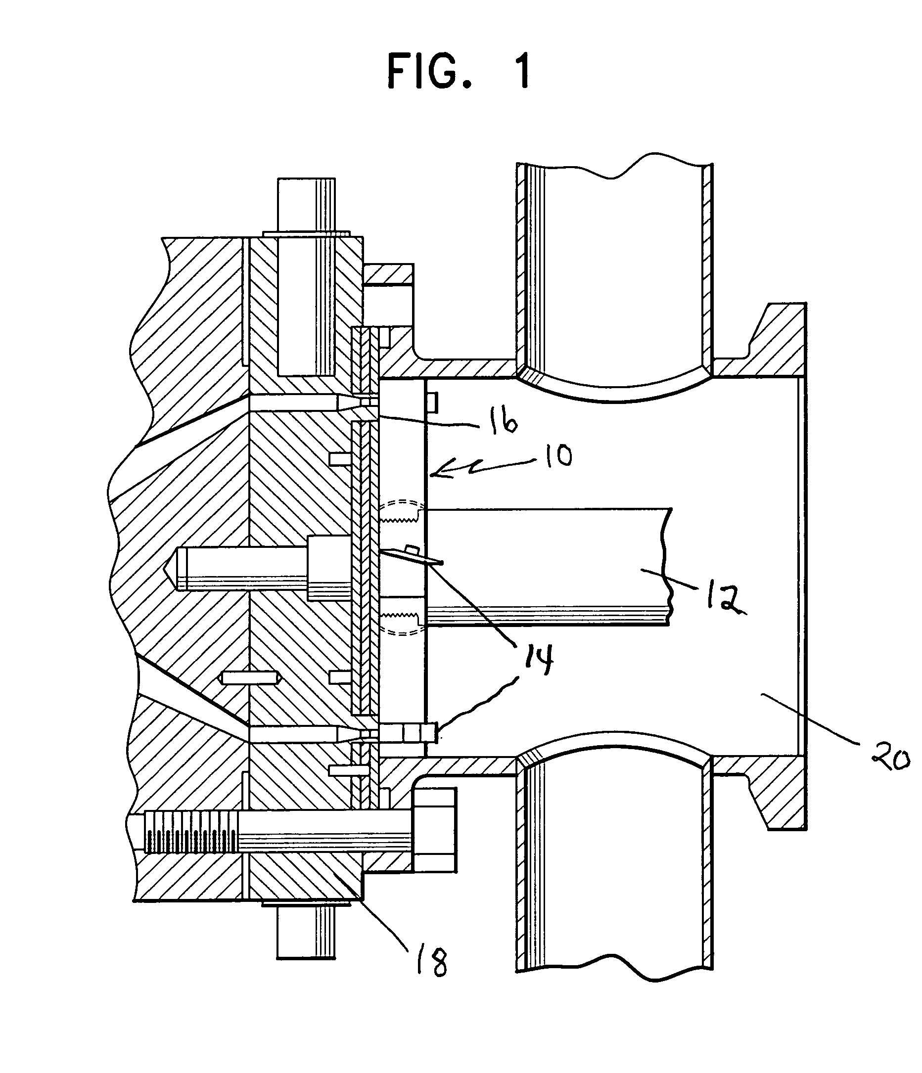
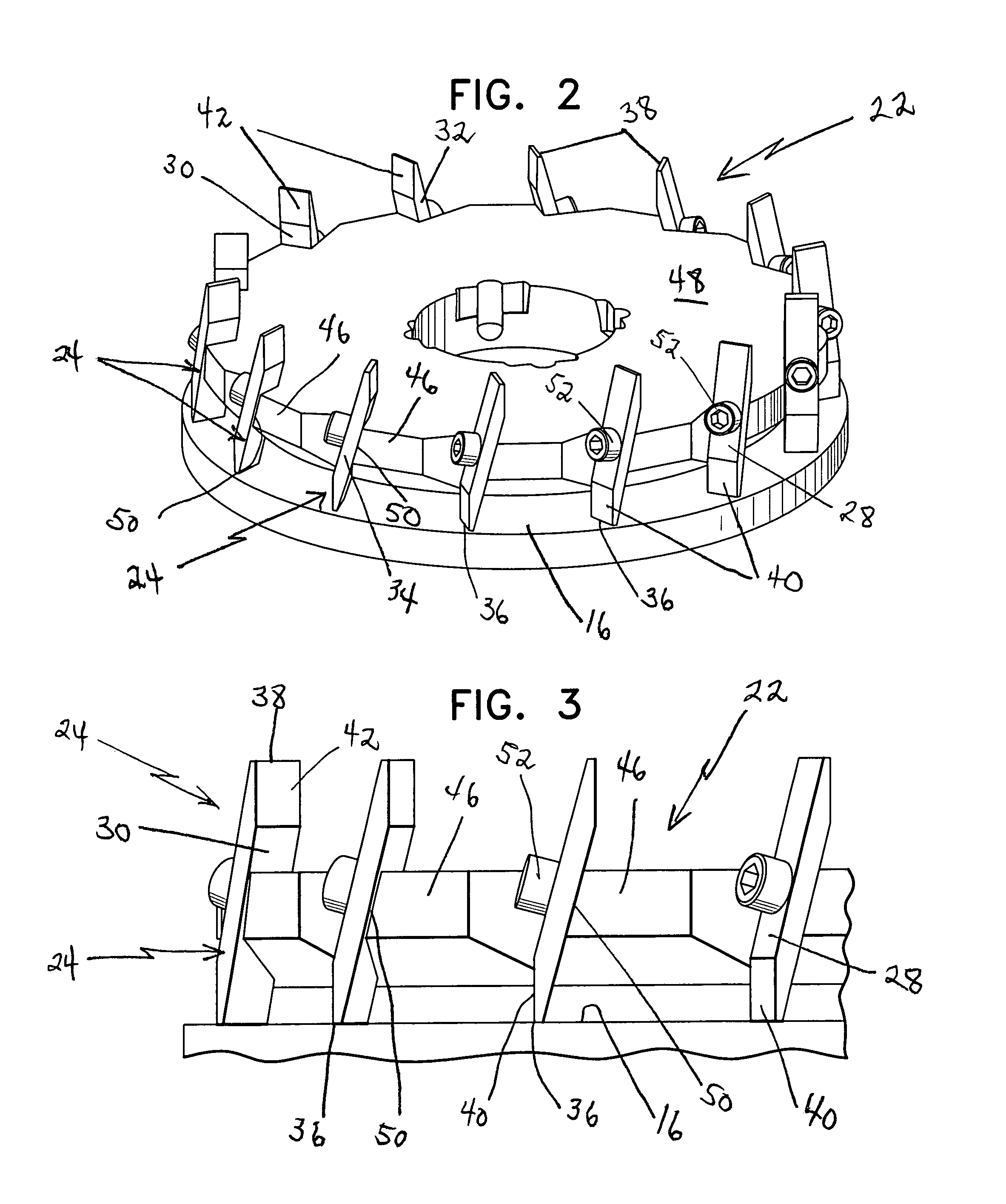
[0041]A cutter hub and blade assembly applicable for the present invention is generally designated by reference numeral 10 and illustrated in its manner of use in FIG. 1. Such overall structure is more specifically disclosed in U.S. Pat. Nos. 4,123,207 and 4,251,198 with such disclosures expressly being incorporated by reference in this specification as if fully set forth herein in their entirety. The underwater pelletizer includes a drive shaft 12 for driving the cutter hub and blade assembl...


PUM

PropertyMeasurementUnit
steep angleaaaaaaaaaa
bevel angleaaaaaaaaaa

Abstract

A cutter hub and blade assembly for cutting polymer strands extruded from a die face in a pelletizer has cutter blades mounted on the cutter hub at a steep angle. The blades are beveled along a portion of their leading edge to form a blunt cutting edge or surface to the blades which is generally perpendicular to the die face. By beveling the leading edge of a blade supported at a steep angle to form a blunt cutting edge, the bottom surface area of the blade in contact with the die face can be significantly reduced. The reduced contact area provides several advantages including a clean cut of the pellets and a faster blade grinding when seating the blades to the die face.

Description

BACKGROUND OF THE INVENTION[0001]1. Field of the Invention[0002]The present invention relates generally to a rotating cutter hub and blade assembly used in a pelletizer in which a molten polymer is extruded as strands through orifices in a die plate and the strands are cut into pellets with the cutter blades. In this invention, the cutter blades are generally parallelepiped in cross-section and are mounted on the cutter hub at a steep angle to the die face. The front side or leading edge surface of each blade is beveled to present a blunt, generally perpendicular leading or cutting edge or surface to contact and shear the extruded strands along the die face.[0003]2. Description of the Prior Art[0004]The use of a cutter hub with a plurality of blades mounted thereon in association with the die face of a die plate in an underwater and other pelletizers is well known. U.S. Pat. No. 4,123,207 discloses initial developments of a cutter hub supporting a plurality of replaceable cutter bla...

Claims


Application Information

Patent Timeline
Patent Type & Authority Patents(United States)
IPC IPC(8): B29B9/10
CPCB29B9/065B26D7/2614B26D1/0006B26D1/29B26D2001/0033
Inventor FRIDLEY, MICHAEL A.MARTIN, J. WAYNECHANG, TSUNG DANIEL CHENG
Owner GALA INDUSTRIES INC
Why Eureka
Try Eureka