
Method and apparatus for determining load current in a CPU core voltage regulator

a load current and cpu core technology, applied in the direction of dc-dc conversion, power conversion systems, instruments, etc., can solve the problems of discontinuous high-side switch current, reduce the efficiency of synchronous buck converters, and add complexity to converters

Inactive Publication Date: 2007-09-11
SEMTECH CORP
View PDF3 Cites 41 Cited by
  • Summary
  • Abstract
  • Description
  • Claims
  • Application Information

AI Technical Summary

Problems solved by technology

A significant drawback of this approach is that the sensing resistor wastes the output energy and thereby reduces the efficiency of the synchronous buck converter.
A drawback of this approach is that the high-side switch changes state at a relatively high rate (e.g., greater than 250 KHz) and, as a result, the high-side switch current is discontinuous.
Not only does this add complexity to the converter, but there is also a time delay in regulating the output current that diminishes the stability of the converter.
Additionally, this approach becomes difficult to implement and hence impractical at very high switching rates (e.g., approximately 1 GHz) due to bandwidth requirements.
While this approach provides an accurate measurement of output current, it is generally too slow to provide effective information for current load control.

Method used


Image

  • Method and apparatus for determining load current in a CPU core voltage regulator
  • Method and apparatus for determining load current in a CPU core voltage regulator
  • Method and apparatus for determining load current in a CPU core voltage regulator

Examples


Embodiment Construction

[0018]The present invention satisfies the need for a way to provide real-time output current and power measurement for a DC-to-DC power converter having active voltage positioning. In the detailed description that follows, like element numerals are used to describe like elements illustrated in one or more of the drawings.

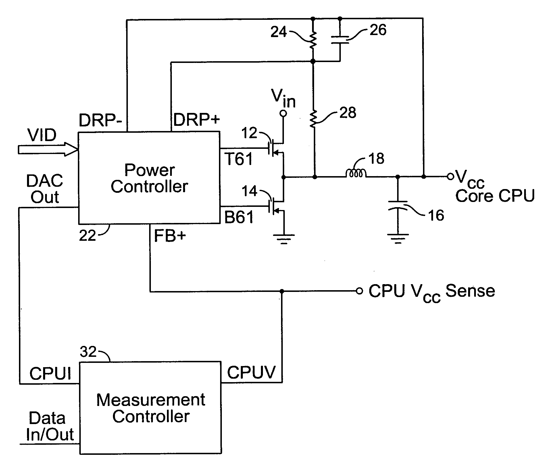
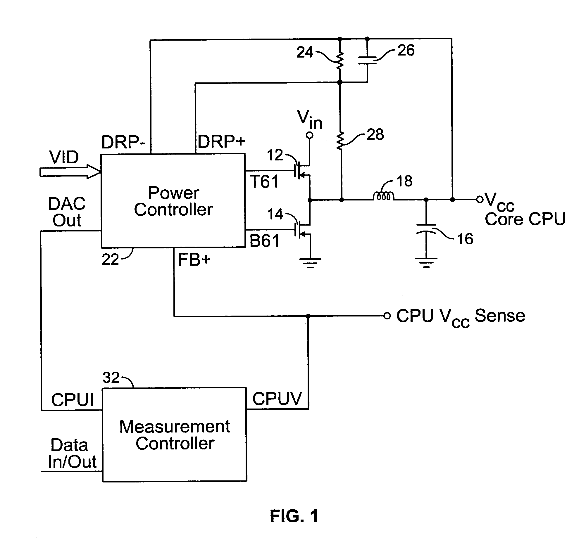
[0019]Referring first to FIG. 1, a schematic diagram is shown of a DC-to-DC voltage converter in accordance with an embodiment of the present invention. The DC-to-DC voltage convert provides an output voltage VCC to a core CPU. The DC-to-DC voltage converter includes a high-side switch 12 and a low-side switch 14 connected to the input voltage source VIN. The high-side switch 12 and the low-side switch 14 are provided by respective MOSFET devices, with the drain of high-side switch 12 connected to the input voltage source VIN, the source of the high-side switch 12 connected to the drain of the low-side switch 14, and the source of the low-side switch 14 connected to...


PUM


Abstract

An apparatus and method for measuring output current and power in real-time is provided for a CPU core powered by a DC-to-DC power converter having active voltage positioning. In an embodiment of the invention, a switched mode power converter comprises at least one power switch operatively coupled to an input voltage source, an output filter operatively coupled to the at least one power switch to provide an output voltage and output current to a load, and a control circuit coupled to the at least one power switch. The control circuit activates the power switch with a duty cycle controlled to regulate at least one of the output voltage and the output current. The control circuit receives a first control signal defining a desired value for the output voltage, a second control signal defining a relationship between voltage input and current draw for the load, and a voltage sense signal corresponding to an actual value of the output voltage. The control circuit thereby provides a measurement of load current.

Description

RELATED APPLICATION DATA[0001]This patent application claims priority pursuant to 35 U.S.C. § 119(c) to provisional patent application Ser. No. 60 / 552,780, filed Mar. 11, 2004.BACKGROUND OF THE INVENTION[0002]1. Field of the Invention[0003]The present invention relates to DC-to-DC power converter circuits for regulating central processing unit (CPU) core voltages, and more particularly, to the determination of load current and power consumption by a CPU core without use of a sense resistor.[0004]2. Description of Related Art[0005]Switched mode DC-to-DC power converters are commonly used in the electronics industry to convert an available direct current (DC) level voltage to another DC level voltage. A switched mode converter provides a regulated DC output voltage by selectively storing energy by switching the flow of current into an output inductor coupled to a load. A synchronous buck converter is a particular type of switched mode converter that uses two power switches, such as MO...

Claims


Application Information

Patent Timeline
Patent Type & Authority Patents(United States)
IPC IPC(8): G05F1/565G05F1/618G05F1/40H02M3/156
CPCH02M3/156H02M2001/0009H02M1/0009
Inventor HORNER, JON
Owner SEMTECH CORP
Learn More