Shielded RFID transceiver with illuminated sensing surface

a technology of sensing surface and shielded rfid transceiver, which is applied in the direction of instruments, burglar alarm mechanical actuation, audible signalling system, etc., can solve the problems of degrading the reading range to an rfid tag, no means for visual indication integrated with the sensing surface, and energy loss of tuned antenna circuit, etc., to achieve the effect of maintaining immunity to metal in the panel, extending the sensing range, and reducing the metal

Inactive Publication Date: 2007-09-11
INDONESIA STOCK EXCHANGE
View PDF8 Cites 40 Cited by
  • Summary
  • Abstract
  • Description
  • Claims
  • Application Information

AI Technical Summary

Problems solved by technology

Placing display circuitry in close proximity to an RFID transceiver antenna could adversely interact with the antenna by reducing the Q (quality factor) of its resonance through coupling the transmitted energy into the display circuitry resulting in energy loss from the tuned antenna circuit.
Additionally, a high Q antenna implicitly means that it is narrow band and susceptible to the possibility that metal in the local vicinity may change the tuning of the central resonant frequency of the antenna away from the operating frequency of the RFID system thus degrading the reading range to an RFID tag.
Mounting an industrial inductive proximity sensor through a metal panel has analogous problems to that of the RFID reader and similarly requires the need for immunity of the sensor to surrounding metal.
There is no means for visual indication integrated with the sensing surface.
Despite the considerable effort that has been applied heretofore in the design of RFID transceivers none have produced a compact RFID reader that can be mounted through a metal panel and integrate status indication into the sensor face without having the antenna be adversely affected by the presence of the status indicator within the transmitted field or adversely affected by the proximity of the metal in a panel when being mounted therethrough.
Many applications for RFID validation are considerably space limited.
Finally, many applications for RFID validation do not have other suitable displays available to indicate the status of the sensor or of the information transacted and must rely on a status indicator integrated into the reader.

Method used


Image

  • Shielded RFID transceiver with illuminated sensing surface
  • Shielded RFID transceiver with illuminated sensing surface
  • Shielded RFID transceiver with illuminated sensing surface

Examples


Embodiment Construction

[0028]Within the description of the invention that follows, the following definitions and meanings will be used. The terms RFID reader and RFID transceiver will have the same meaning. An RFID tag includes an RFID transponder circuit, an antenna, and the physical package enclosing them. RF energy received by the transceiver includes that of a transponder modulating its antenna impedance to cause a time varying portion of the RF energy transmitted by the transceiver to be reflected back to the transceiver. A light pipe is a transparent conduit for conducting light on a path from an entrance aperture to an exit aperture utilizing total internal reflection properties to channel the light along the path, wherein the light pipe is a material of a higher index of refraction surrounded by a material (including air) of a lower index of refraction.

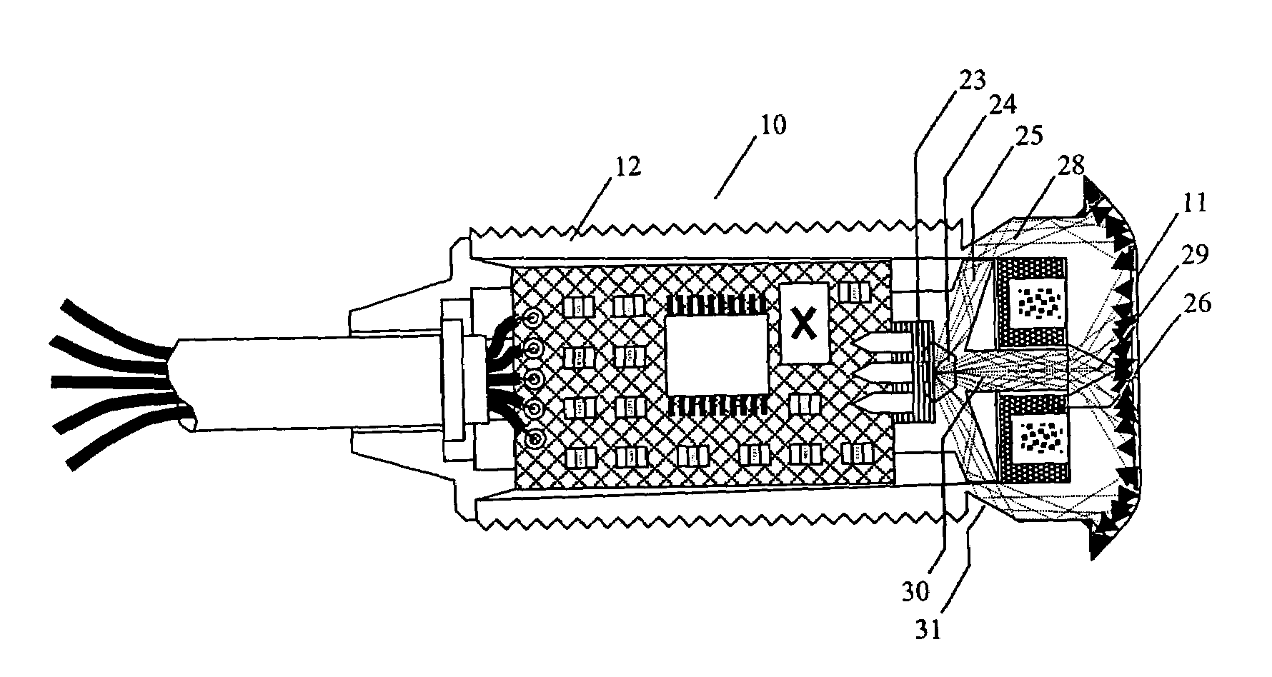
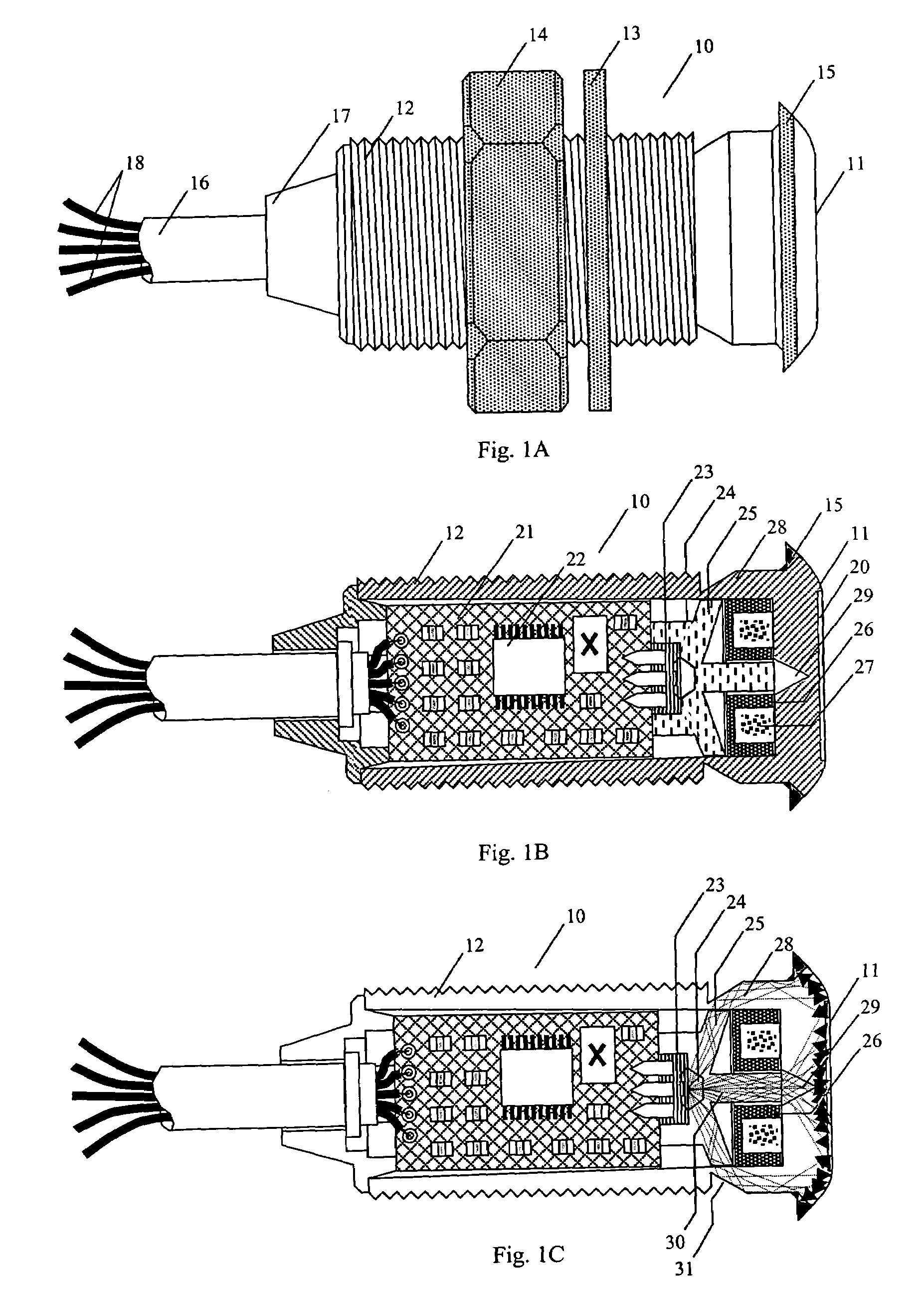
[0029]An RFID transceiver 10 having sensing surface 11 is shown in FIG. 1A. A threaded tubular body 12 of the RFID transceiver is designed for thro...


PUM


Abstract

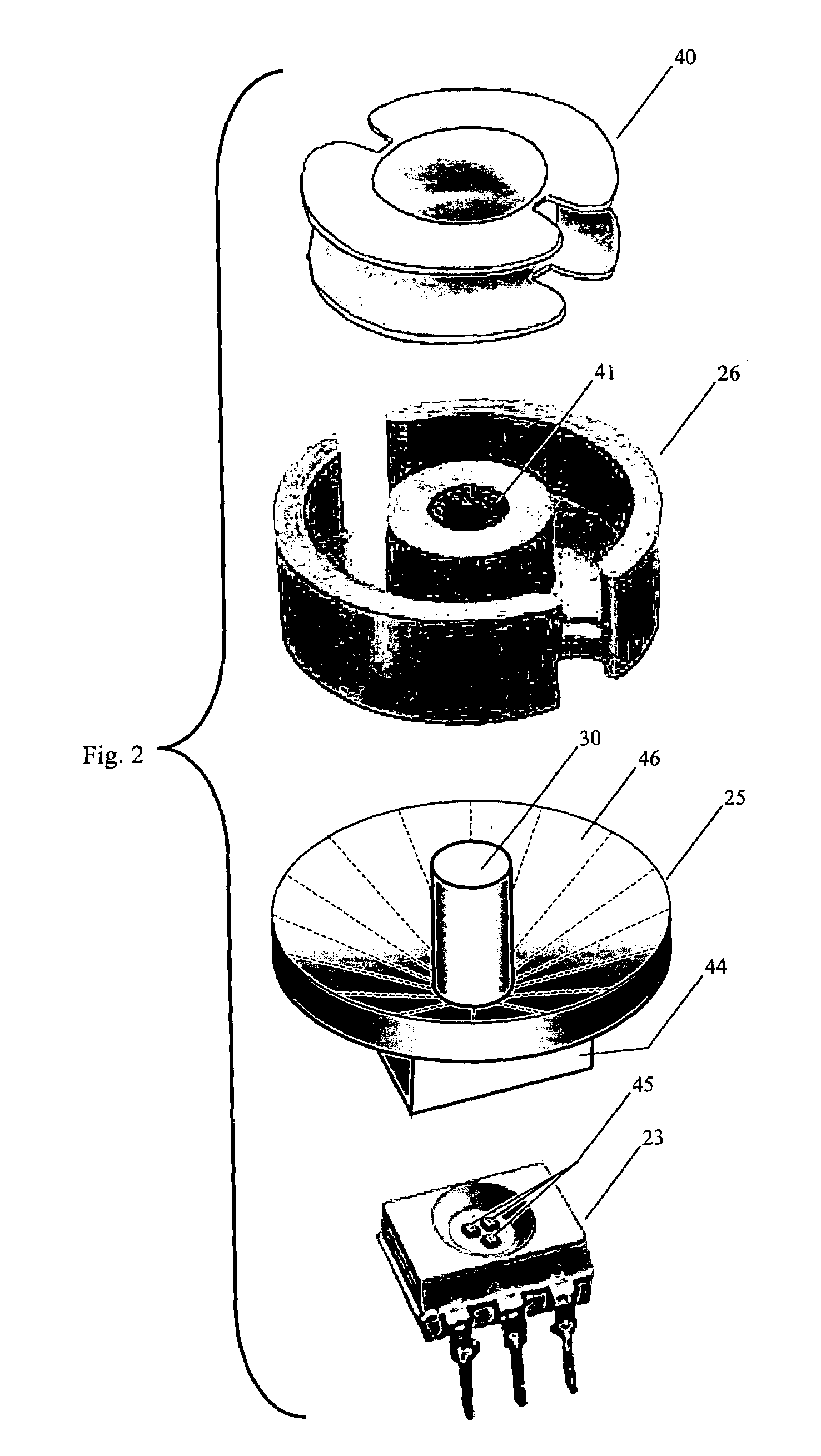
A transceiver for reading RFID tags has a ferrite core antenna substantially circular in cross-section having a transmitting and receiving face producing substantially no RF energy below a plane of the transmitting and receiving face outside a peripheral surface of the ferrite core. A portion of the transceiver enclosure which passes through a mounting panel opening functions as light pipe for conducting LED indicator light in a substantially radially symmetrical manner to illuminate a sensing surface of the transceiver.

Description

FIELD OF THE INVENTION[0001]This invention pertains to RFID transceivers, and in particular to panel mounted RFID transceivers adapted for a relatively small footprint, antenna tuning immunity to nearby metal, and an illuminated sensing surface for indicating transaction status.BACKGROUND OF THE INVENTION[0002]RFID tags are rapidly becoming quite important for tracking and identifying goods as well as for identifying customer accounts. Small tags having a transponder chip and antenna offer many advantages over simple bar codes, including unique serialization, non-contact reading through an outer packaging material, and on-chip storage of information for some transponder chip versions. RFID tags have proven themselves to be quite useful in a wide variety of applications, including those such as bin identification, pallet identification, product serialization, access card identification, and account identification.[0003]Just as RFID tag application breath is wide, so also is the envir...

Claims


Application Information

Patent Timeline
Patent Type & Authority Patents(United States)
IPC IPC(8): G08B13/14
CPCG08B13/24
Inventor JUDS, SCOTT
Owner INDONESIA STOCK EXCHANGE
Why Eureka
Try Eureka