Digital camera for changing a recording size to a high-sensitivity compatible recording size

Active Publication Date: 2007-09-11
FUJIFILM CORP
View PDF3 Cites 22 Cited by
  • Summary
  • Abstract
  • Description
  • Claims
  • Application Information

AI Technical Summary

Benefits of technology

[0061]As described above, the digital camera of the present invention prevents photographing e

Problems solved by technology

However, a large number of users are unfamiliar with such correlationship between the sensitivity setting and the reco

Method used


Image

  • Digital camera for changing a recording size to a high-sensitivity compatible recording size
  • Digital camera for changing a recording size to a high-sensitivity compatible recording size
  • Digital camera for changing a recording size to a high-sensitivity compatible recording size

Examples


Example

[0069]Embodiments of digital camera of the present invention will be described below.

[0070]First, description will be given of an embodiment common to a first, second, third, and fourth digital cameras of the present invention.

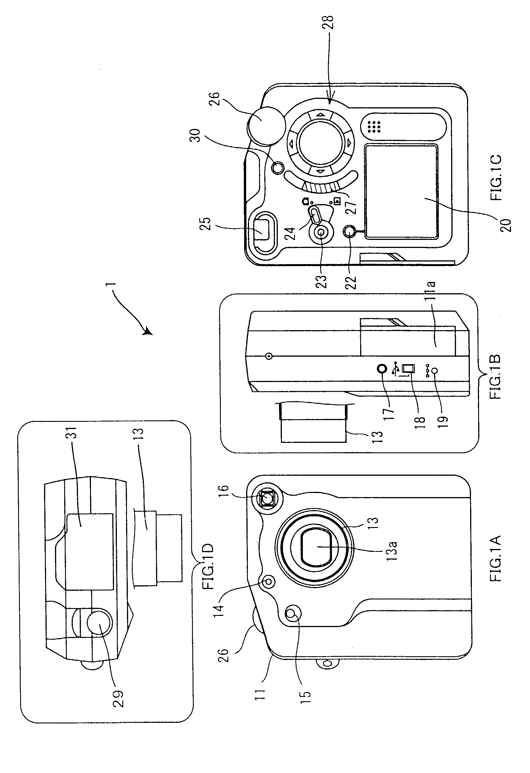
[0071]FIGS. 1A to 1D are a front view, a left side view, a rear view, and a top view, respectively, of a digital camera 1 of this embodiment.

[0072]The front view in FIG. 1A shows a camera enclosure 11, a lens barrel 13 containing a photographing lens 13a, a finder objective window 16, a flash light receiving window 14, a self timer lamp 15 having a blink speed which varies depending on the time remaining before the start of a photographing process if a self timer function has been activated, and a photographing mode dial 26 that switches six types of photographing modes, described later. The flash light receiving window 14 is used to guide flash light to a flash light receiving sensor that detects the quantity of returning flash light reflected by an object du...


PUM


Abstract

The present invention provides a digital camera that prevents photographing errors attributed to an increase in sensitivity effected by reducing the recordable image size. In a digital camera that allows a high sensitivity to be set by pixel mixture, a display is provided to prevent photographing errors caused by restrictions or the like resulting from setting of a high sensitivity.

Description

BACKGROUND OF THE INVENTION[0001]1. Field of the Invention[0002]The present invention relates to a digital camera that takes a photograph by forming an image of an object on a solid imaging device.[0003]2. Description of the Related Art[0004]Because of the reduced size and costs of their unit light receiving elements, digital cameras have recently been popular which take a photograph by forming an image of an object on a solid imaging device composed of a set of a plurality of two-dimensionally arranged unit light receiving elements to obtain image data representing this object. These digital cameras control exposure according to sensitivity set by, for example, selecting an ISO (International Organization for Standardization) value from a menu display.[0005]If a high sensitivity is set, some of these digital cameras actualize this high sensitivity by increasing the time for which charges remain stored in the solid imaging device (for example, refer to Japanese Patent Laid-Open No. ...

Claims


Application Information

Patent Timeline
IPC IPC(8): H04N5/262H04N5/222H04N5/232H04N5/235
CPCH04N5/23293H04N5/235H04N5/2355H04N23/633H04N23/631H04N23/70H04N23/741
Inventor YOSHIDA, MASANORI
Owner FUJIFILM CORP
Why Eureka
Try Eureka