
Fuel injection control apparatus for direct injection type internal combustion engine

a technology of control apparatus and internal combustion engine, which is applied in the direction of electric control, lubrication of crankcase compression engine, instruments, etc., can solve the problem of difficulty in obtaining estimated results having sufficiently high accuracy

Active Publication Date: 2007-09-11
TOYOTA JIDOSHA KK
View PDF23 Cites 12 Cited by
  • Summary
  • Abstract
  • Description
  • Claims
  • Application Information

AI Technical Summary

Problems solved by technology

With such a fuel injection control apparatus, it is difficult to obtain estimated results having sufficiently high accuracy.

Method used


Image

  • Fuel injection control apparatus for direct injection type internal combustion engine
  • Fuel injection control apparatus for direct injection type internal combustion engine
  • Fuel injection control apparatus for direct injection type internal combustion engine

Examples


first embodiment

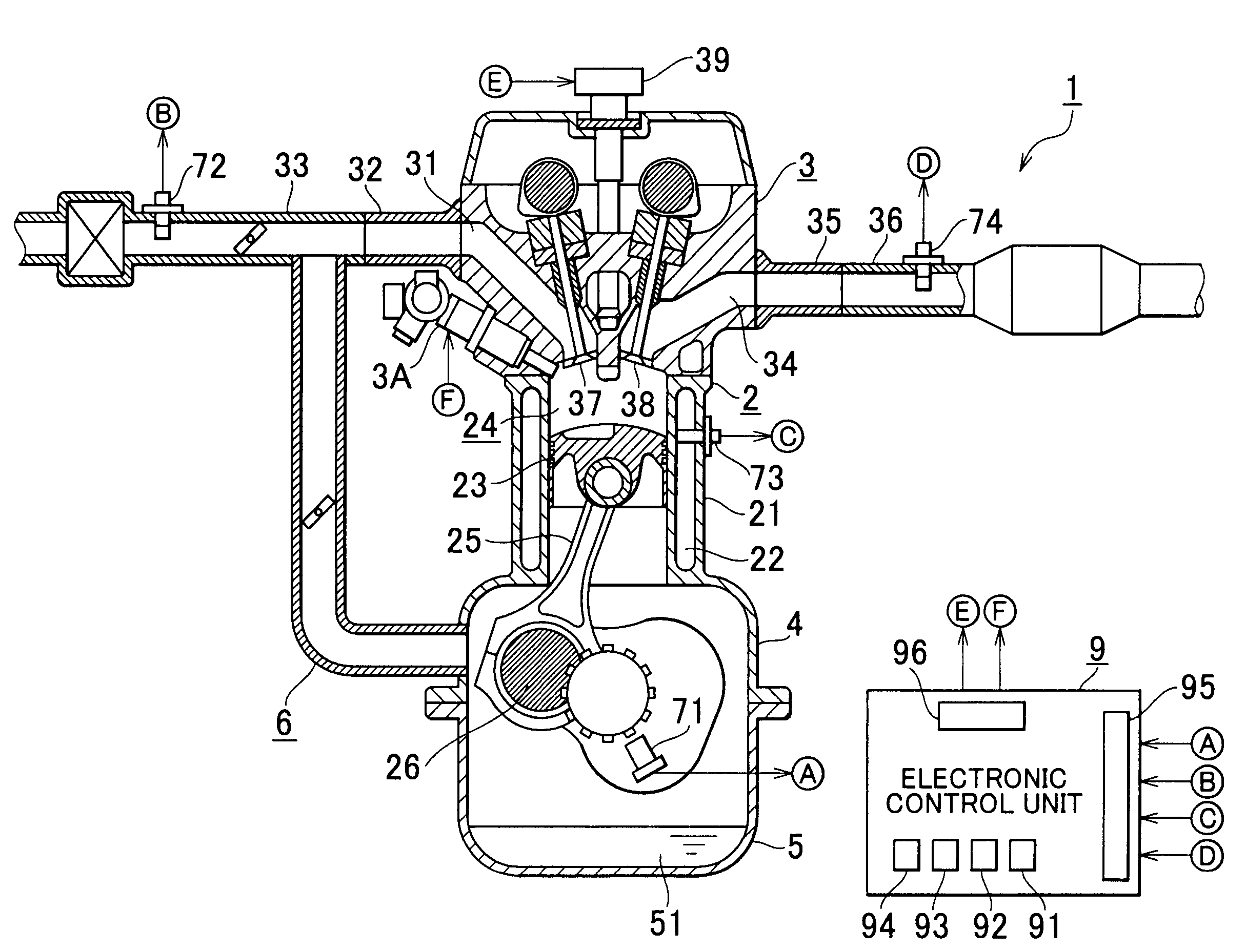
[0026]Hereafter, the invention will be described with reference to FIG. 1 to FIG. 5.

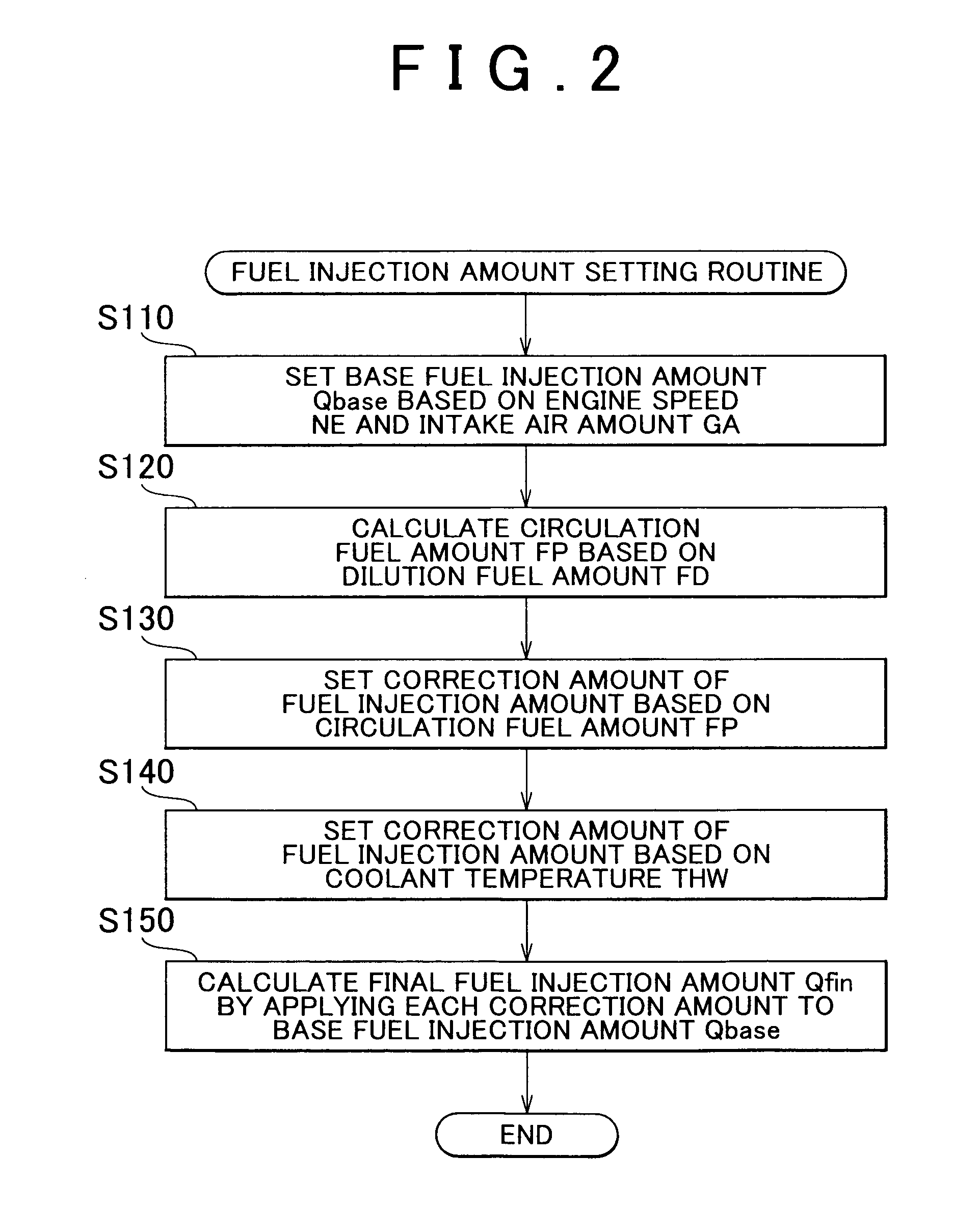
[0027]According to the first embodiment, the degree of fuel dilution can be accurately estimated by estimating the amount of fuel that has mixed with the lubricating oil (hereinafter, such fuel will be referred to as “dilution-fuel”). It is also possible to estimate the increase in the amount of dilution-fuel after an engine was started, through the “dilution-fuel increase amount estimating routine” which will be described later in detail.

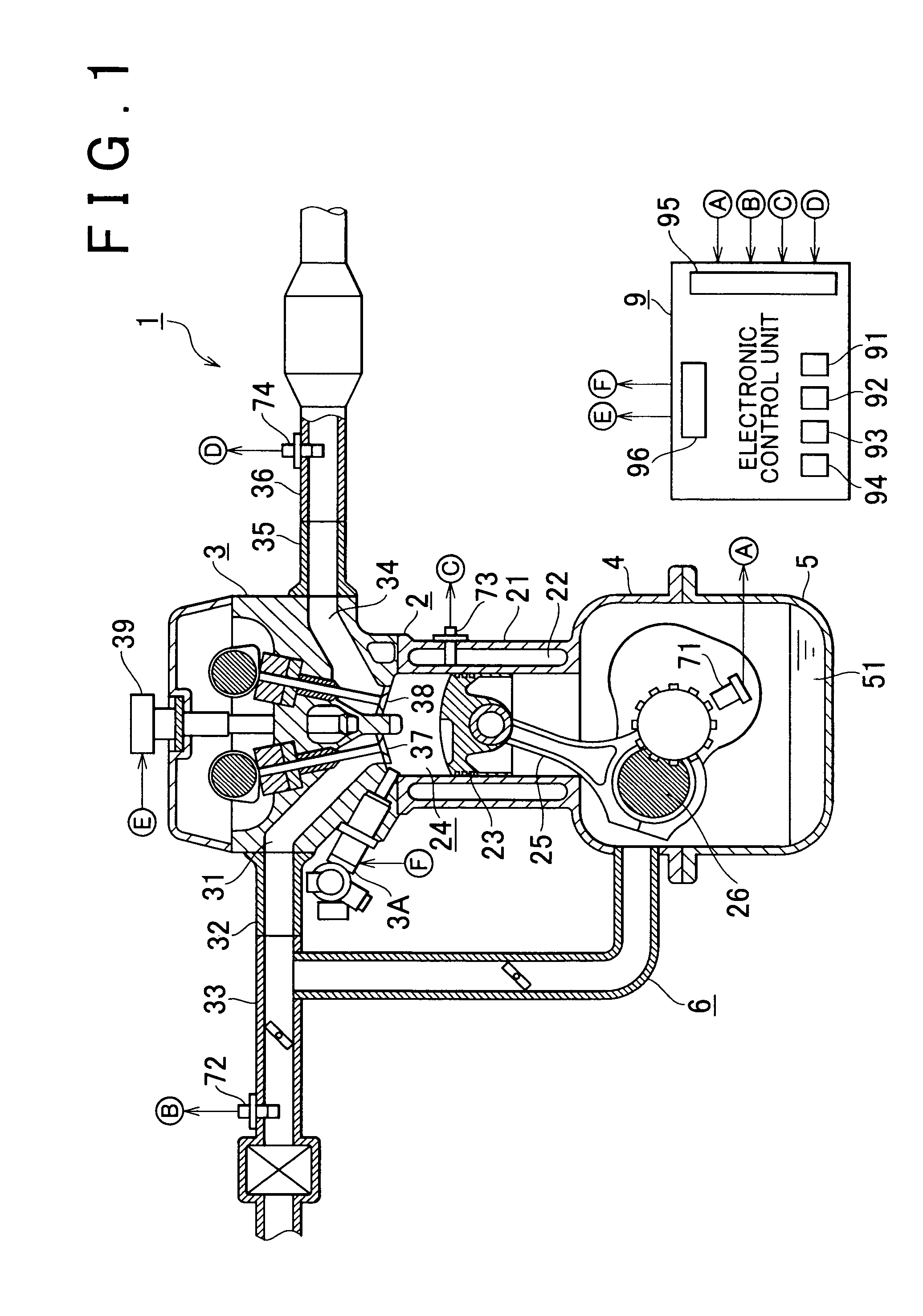
[0028]FIG. 1 shows the structure of an engine 1 (i.e., a direct injection type internal combustion engine). The engine 1 includes a cylinder block 2 and a cylinder head 3.

[0029]The cylinder block 2 is provided with a plurality of cylinders 21. A water jacket 22 is formed in each of the cylinders 21. A piston 23 is provided in each cylinder 21. A combustion chamber 24 is defined by the inner surface of the cylinder 21, the top surface of the piston 23, and the cylind...


PUM


Abstract

A fuel injection control apparatus for a direct injection type internal combustion engine according to the invention includes a control unit. The control unit estimates the degree to which lubricating oil, which is used in the internal combustion engine, has been diluted with fuel based on the length of time the internal combustion engine has been running, and an accumulated value that indicates an amount of air that has been taken in by the internal combustion engine while the internal combustion engine has been running or an accumulated value that indicates an amount of fuel that has been injected while the internal combustion engine has been running. The control unit determines the amount of fuel to be injected based on the degree of dilution.

Description

INCORPORATION BY REFERENCE[0001]The disclosure of Japanese Patent Application No. 2004-377308 filed on Dec. 27, 2004 including the specification, drawings and abstract is incorporated herein by reference in its entirety.BACKGROUND OF THE INVENTION[0002]1. Field of the Invention[0003]The invention relates to a fuel injection control apparatus for a direct injection type internal combustion engine in which fuel is injected directly into the combustion chamber.[0004]2. Description of the Related Art[0005]In a direct injection type internal combustion engine, if the fuel injected from an injector is not sufficiently atomized, a large amount of fuel adheres to the inner surface of the cylinder, and the fuel is mixed into lubricating oil. As a result, the lubricating oil is diluted with the fuel, also known as “fuel dilution”.[0006]Therefore, fuel injection control apparatuses that estimate the degree of such fuel dilution have been proposed. For example, Japanese Patent Application Publi...

Claims


Application Information

Patent Timeline
Patent Type & Authority Patents(United States)
IPC IPC(8): F02D41/38
CPCF02D41/047F02D41/06F02D41/403F02D2250/11Y02T10/44Y02T10/40
Inventor HONDA, KOJITERAOKA, MASAHIKOIDOGAWA, MASANAOHIROWATARI, SEIJI
Owner TOYOTA JIDOSHA KK
Learn More