
Supplying power to at least one electrical device based on an efficient operating point of a power supply

a technology of power supply efficiency and power supply, applied in the field of power systems, can solve the problems of increased energy costs, loss of power factors less than 1 and loss of power during conditioning

Active Publication Date: 2007-09-11
HEWLETT-PACKARD ENTERPRISE DEV LP
View PDF13 Cites 27 Cited by
  • Summary
  • Abstract
  • Description
  • Claims
  • Application Information

AI Technical Summary

Benefits of technology

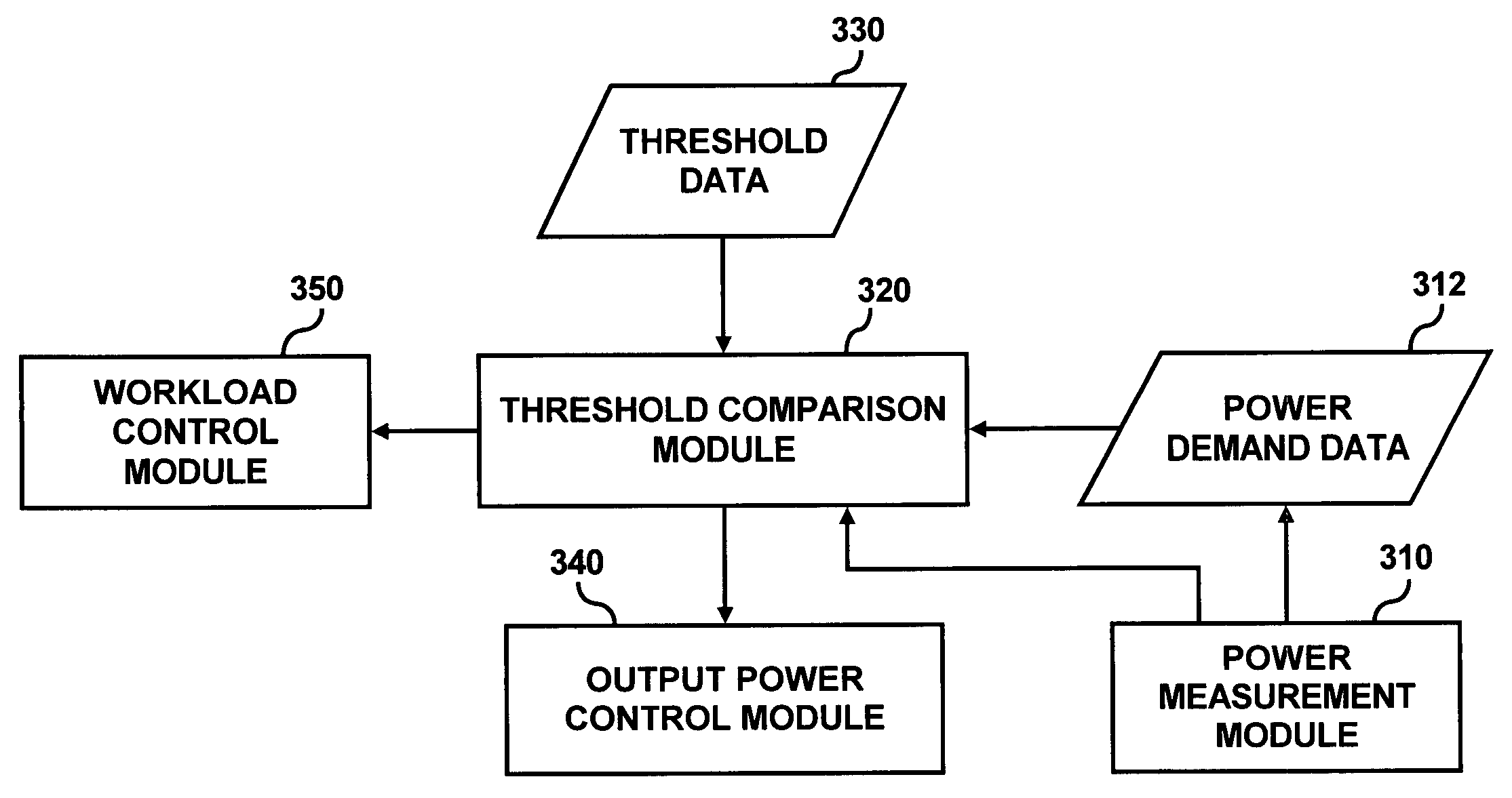
[0012]According to another embodiment, an apparatus controls the power output from a first and second power supply based on an efficiency of the first power supply. The first and second power supply provide power to at least one electrical device. The apparatus comprises at least one power measuring circuit measuring a power demand of the at least one electrical device, a memory storing at least one threshold associated with an efficient operating point of the first power supply, and a circuit comparing the power demand of the at least one electrical device to the at least one threshold and controlling an output power of the first power supply to substantially maintain the first power supply at the efficient operating point.

Problems solved by technology

However, in reality, losses occur during the conditioning, typically as heat dissipation.
Therefore, conventional power systems for computer systems typically sacrifice efficiency for other factors (e.g., redundancy), which leads to increased energy costs.
However, for non-purely resistive loads, real power is less than apparent power, leading to power factors less than 1.
The difference between apparent and real power impacts the cost of the electrical equipment that provides power to a computer system power supply, because all the electrical components upstream of the power supply must be sized for a higher current.
In addition, because all components dissipate some heat when current passes through them, higher currents translate into greater power wastage.
A poor power factor may be the result of a large amount of reactive power caused by an inductive load.
However, power factor is typically not considered when optimizing the efficiency of a power supply or power system.

Method used


Image

  • Supplying power to at least one electrical device based on an efficient operating point of a power supply
  • Supplying power to at least one electrical device based on an efficient operating point of a power supply
  • Supplying power to at least one electrical device based on an efficient operating point of a power supply

Examples


Embodiment Construction

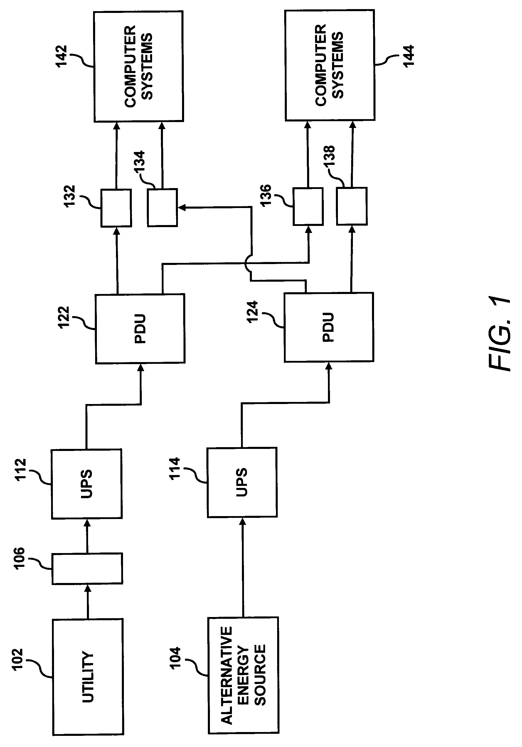
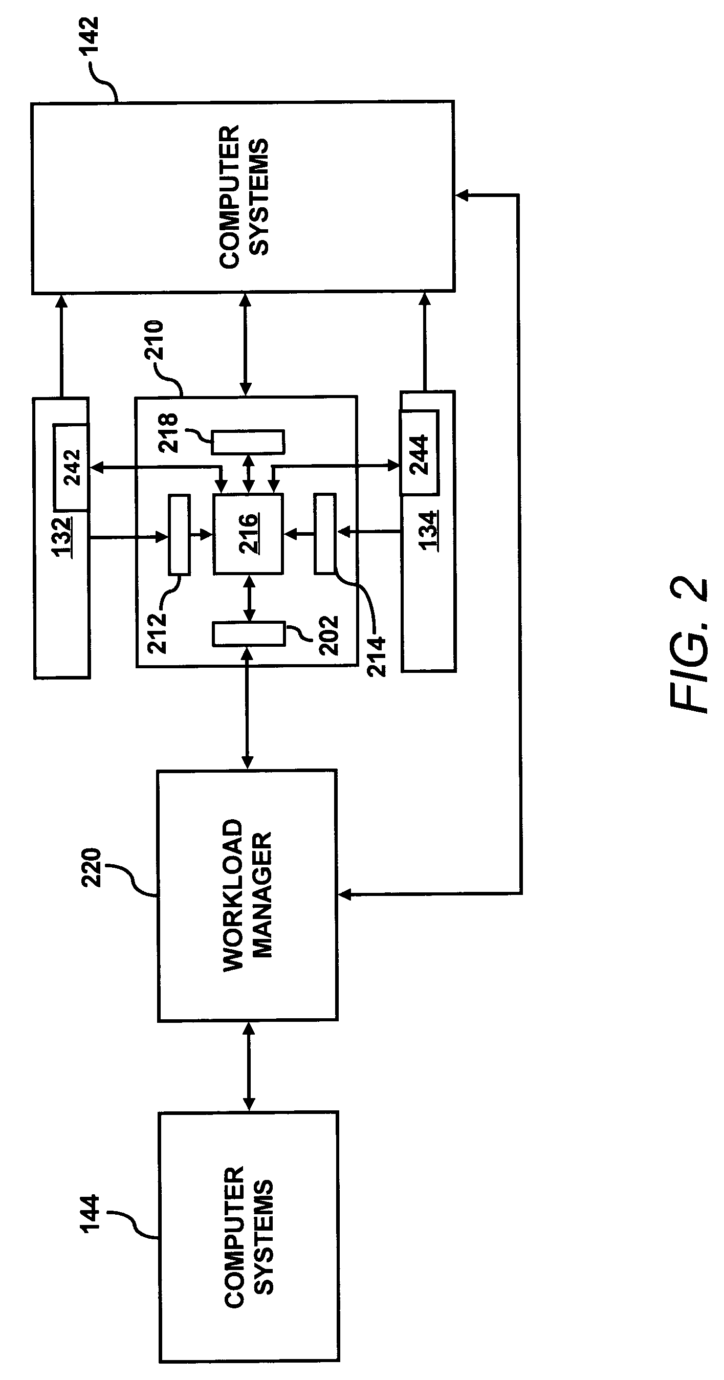
[0022]According to an embodiment, at least two power supplies supply power to at least one computer system. A first power supply of the at least two power supplies is substantially maintained at an efficient operating point when supplying power to the computer systems. When the efficiency of the first power supply varies from the efficient operating point, the load of the first power supply is changed to allow the first power supply to return to the efficient operating point.

[0023]In one embodiment, the load on the first supply is changed by using a second power supply to supply power to the computer systems. For example, when the power demand of the computer systems exceeds the output power of the first power supply operating at the efficient operating point, then the second power supply additionally supplies power to the computer systems (i.e., the second power supply shares the load). Generally, the amount of power demand exceeding the power output of the first power supply opera...


PUM


Abstract

A primary power supply and a secondary power supply are operable to supply power to at least one electrical device. A power demand of the electrical device is determined, and an efficient operating point for the primary power supply is determined. One or more of the primary power supply and the secondary power supply are used to supply power to the electrical device based on whether the primary power supply operating at an efficient operating point is operable to meet the power demand of the at least one electrical device.

Description

FIELD OF THE INVENTION[0001]This invention relates generally to power systems. More particularly, the invention relates to supplying power to at least one electrical device based on the efficiency of a power supply.BACKGROUND OF THE INVENTION[0002]Power supplies for computer systems are typically designed to meet the maximum power demand of the load, such as the computer systems receiving power from the power supplies, and for redundancy. While these factors are important in power supply design, energy efficiency is an equally important factor that is usually not given the same weight as other factors when designing power supplies.[0003]FIG. 5 illustrates a conventional power supply 500 modeled as a black box with power entering the black box (input power) and conditioned power (output power) exiting the black box. Conditioning may include alternating current (A / C) or direct current (D / C) conversions (e.g., AC / AC, AC / DC, DC / DC, etc.), and the like. Ideally, there would be no losses ...

Claims


Application Information

Patent Timeline
Patent Type & Authority Patents(United States)
IPC IPC(8): G06F1/26H02J1/10H02M1/00
CPCG06F1/263H02J1/10H02M1/4208Y02B70/126Y02B70/10
Inventor JANAKIRAMAN, GOPALAKRISHNANFARKAS, KEITH ISTVANPATEL, CHANDRAKANT D.BASH, CULLEN EDWIN
Owner HEWLETT-PACKARD ENTERPRISE DEV LP
Learn More