Electromagnetic flow meter for low conductivity fluids

a low conductivity fluid and flow meter technology, applied in the field of electromagnetically driven flow meters, can solve the problems of small reduction, change in measured potential, and inability or undesirable, and achieve the effect of increasing the length of the electrode and reducing the effective electrode impedan

Inactive Publication Date: 2006-10-10
STONEFIELD WORKS
View PDF9 Cites 14 Cited by
  • Summary
  • Abstract
  • Description
  • Claims
  • Application Information

AI Technical Summary

Benefits of technology

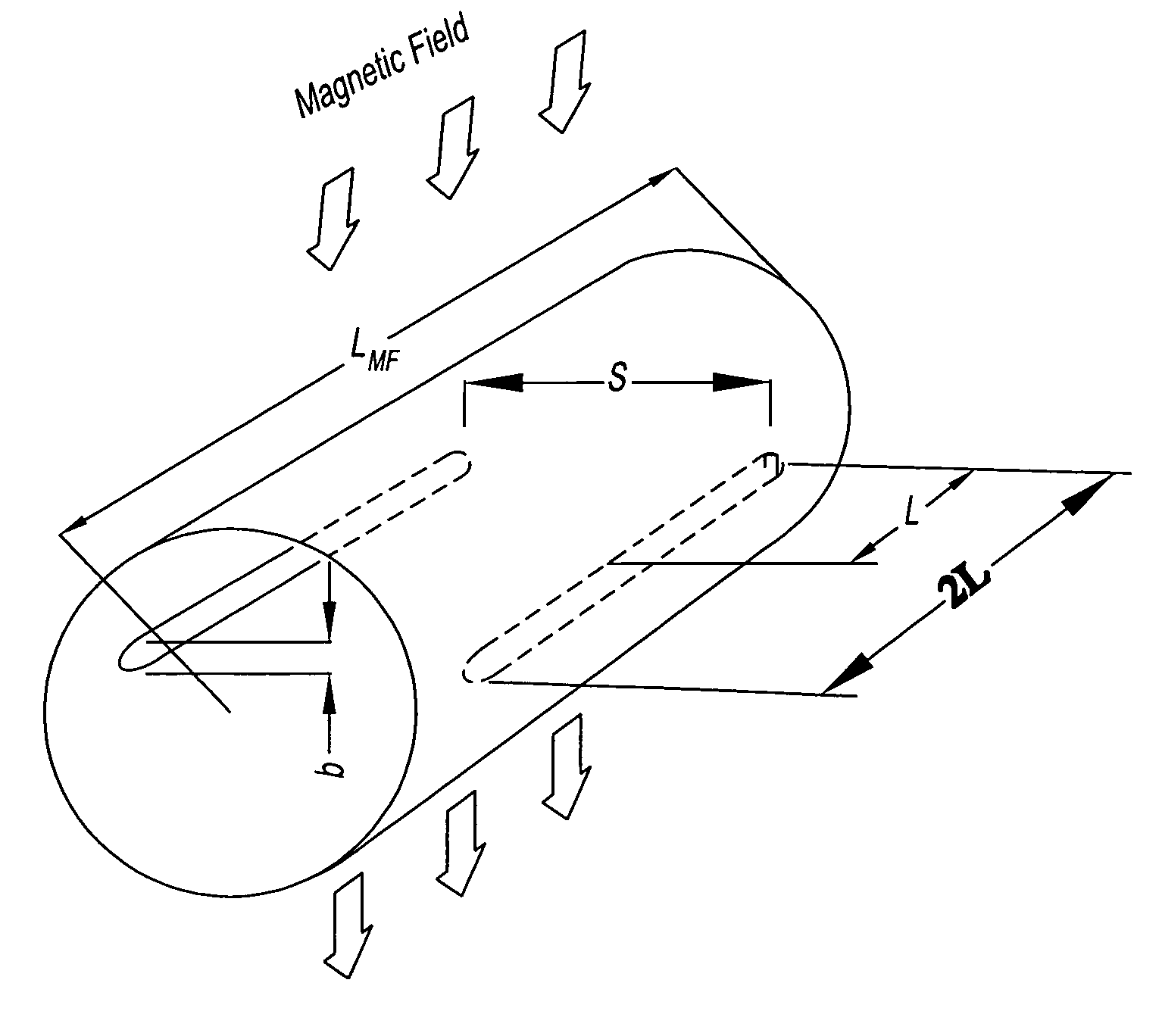
[0025]Pursuant to the invention, it has been appreciated that increasing the length of the electrodes can significantly decrease the effective electrode impedance, by an order of magnitude, without becoming susceptible to the known problems of contamination of a portion of the electrodes associated with prior art “larger” electrodes. Preferably, the electrodes have a length in the direction of elongation of the fluid conduit at least equal to the conduit diameter (or separation of electrodes or equivalent cross-sectional dimension of a non-circular conduit). The electrodes preferably have a length similar to the length of the field generating means, preferably at least half the length of the field generating means, preferably at least three quarters, typically at least 80%, ideally of the order of 90% or more of the length of the field generating means.
[0026]Such a flow meter may be reliably capable of measuring flow in a fluid having conductivity of the order of 10−4 mhos / m or less without the requirement for specialist instrumentation and without being unduly susceptible to noise. Preferably, the flow meter further comprises an input amplifier connected to the potential sensing electrodes having an input impedance of at least 1012 ohms, more preferably of the order of 1015 ohms or more.

Problems solved by technology

However, only a small reduction can be gained (and a significant reduction would be needed) and in any event the change in shape may cause turbulence and / or other flow problems (such as increased flow resistance) and so may not be possible or may be undesirable in many applications.
Furthermore, as the diameter of the electrodes increases, contamination of a portion of an electrode may lead to a change in the measured potential.
Thus, minor changes in the geometry of the meter might lead to small changes in impedance but are likely to introduce problems and so have not appeared to provide a promising route.

Method used


Image

  • Electromagnetic flow meter for low conductivity fluids
  • Electromagnetic flow meter for low conductivity fluids
  • Electromagnetic flow meter for low conductivity fluids

Examples


Embodiment Construction

[0048]To assist in understanding the present invention, a theoretical explanation will first be given.

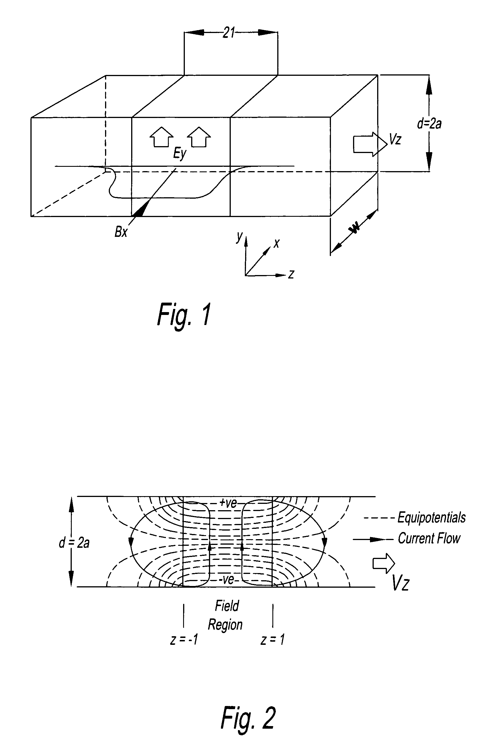
[0049]A magnetic flow meter is in essence a type of M.H.D. (magneto-hydrodynamic) generator. A simple form consists of a duct, lined with an electrically insulating lining through which the fluid to be measured flows, and in operation the fluid is made to pass through a transverse magnetic field within the duct. The moving fluid creates an electric field, E in a direction perpendicular to the motion, and to the magnetic field. The strength of the electric field depends upon the velocity V, and upon the intensity of the field B. Appropriately placed electrodes are connected to electronic apparatus that measures the potential difference between them and converts this into a form that indicates the mean flow through the meter. The details of the electronic apparatus are not germane and many conventional schemes are known which may be used herein.

[0050]FIG. 1 shows the layout of a simpl...


PUM


Abstract

An electromagnetic flow meter is disclosed which can be used to measure flow in low conductivity fluids, for example alcohol, turpentine, oil or other organic solvents. In one embodiment, the electromagnetic flow meter includes an elongate flow conduit having a direction of elongation corresponding to a direction of fluid flow, magnetic field generating means for generating a magnetic field across the flow conduit and potential sensing electrodes for sensing a potential generated by the magnetic field in a fluid flowing through the conduit. Both the field generating means and the potential sensing electrodes of the flow meter are elongate in the direction of flow.

Description

BACKGROUND OF THE INVENTION[0001]1. Field of the Invention[0002]The present invention relates to electromagnetic flow meters.[0003]2. Description of Related Art[0004]Electromagnetic flow meters have been used for many years for measuring the flow of a conductive fluid. Electromagnetic flow meters have a number of advantages over mechanical meters as they can be made relatively compact and without moving parts to wear or become damaged by inclusions within the fluid. Electromagnetic flow meters work on the principle that a magnetic field (which may be static or time-varying) induces an EMF across a moving fluid. As a practical matter however, the EMF is typically small and measuring it with practical instruments without undue sensitivity to noise is a concern.[0005]It conveniently so happens that water-based fluids, which constitute a usefully large proportion of process fluids to be monitored, tend to have a conductivity that can be measured using an electromagnetic flowmeter of con...

Claims


Application Information

Patent Timeline
Patent Type & Authority Patents(United States)
IPC IPC(8): G01F1/58
CPCG01F1/588
Inventor TURNER, ROGER BRYSON
Owner STONEFIELD WORKS
Why Eureka
Try Eureka