Dual coin actuation mechanism with angularly and axially offset coin slots and recesses

a coin actuation mechanism and coin slot technology, applied in the direction of electric actuation, instruments, apparatus for dispensing discrete objects, etc., can solve the problems of loss of revenue to the owner of the vending machine, and none of them seem to provide the optimum solution for the problem at hand

Inactive Publication Date: 2007-09-18
CHANG KIL JAE
View PDF15 Cites 7 Cited by
  • Summary
  • Abstract
  • Description
  • Claims
  • Application Information

AI Technical Summary

Benefits of technology

[0008]The present invention provides a dual coin actuation mechanism designed to satisfy the aforementioned need. The dual coin actuation mechanism of the present invention provides first and second coin slots angularly and axially offset from one another about and along an axis of rotation and first and second coin carrier wheels that respectively have first and second coin recesses angularly and axially offset from one another about and along the axis of rotation. The axially offset relationships between the slots, between the recesses and thus between first and second paths taken by first and second coins, upon rotation of the carrier wheels, going from initial deposit positions, in which the first and second recesses are aligned correspondingly with first and second slots, to a discharge location, obviate the need to provide any blocking device adjacent to either of the slots in view that the first and second coin are not brought into alignment respectively with the second and first slots and thus made inaccessible to a user during their travel along the first and second paths.

Problems solved by technology

A problem exists, however, with the design of these prior art mechanisms.
The first and second coin slots and recesses, by being axially aligned with one another in the common plane, means that necessarily the path of the trailing or second coin at some point during the turning of the handle and rotation of the central shaft and carrier wheel passes the first coin slot where the second coin is accessible to and can be removed by the user without jamming the mechanism, which results in loss of revenue to the owner of the vending machine.
While these prior art devices appear to be satisfactory in use for the specific purposes for which they were designed, none of them seem to provide the optimum solution for the problem at hand.

Method used


Image

  • Dual coin actuation mechanism with angularly and axially offset coin slots and recesses
  • Dual coin actuation mechanism with angularly and axially offset coin slots and recesses
  • Dual coin actuation mechanism with angularly and axially offset coin slots and recesses

Examples


Embodiment Construction

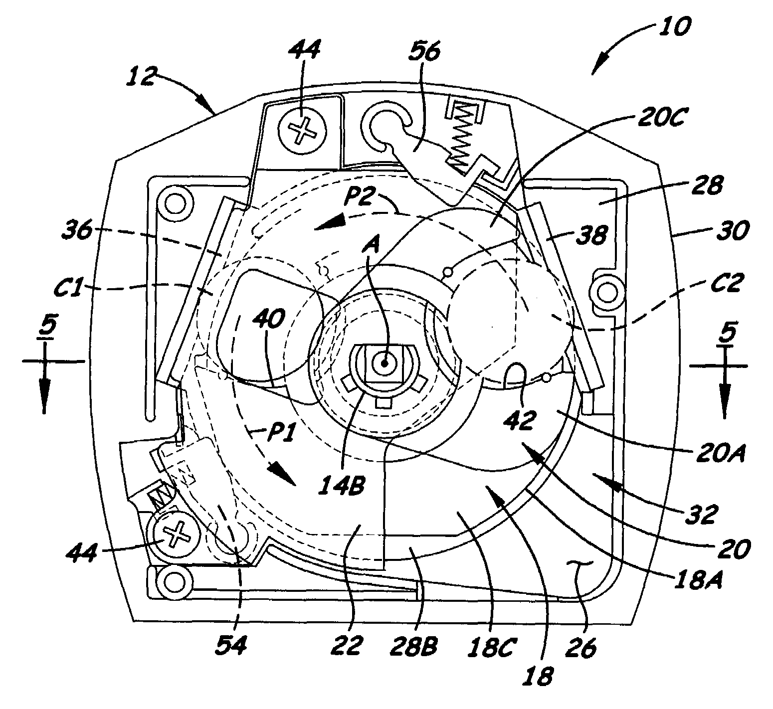
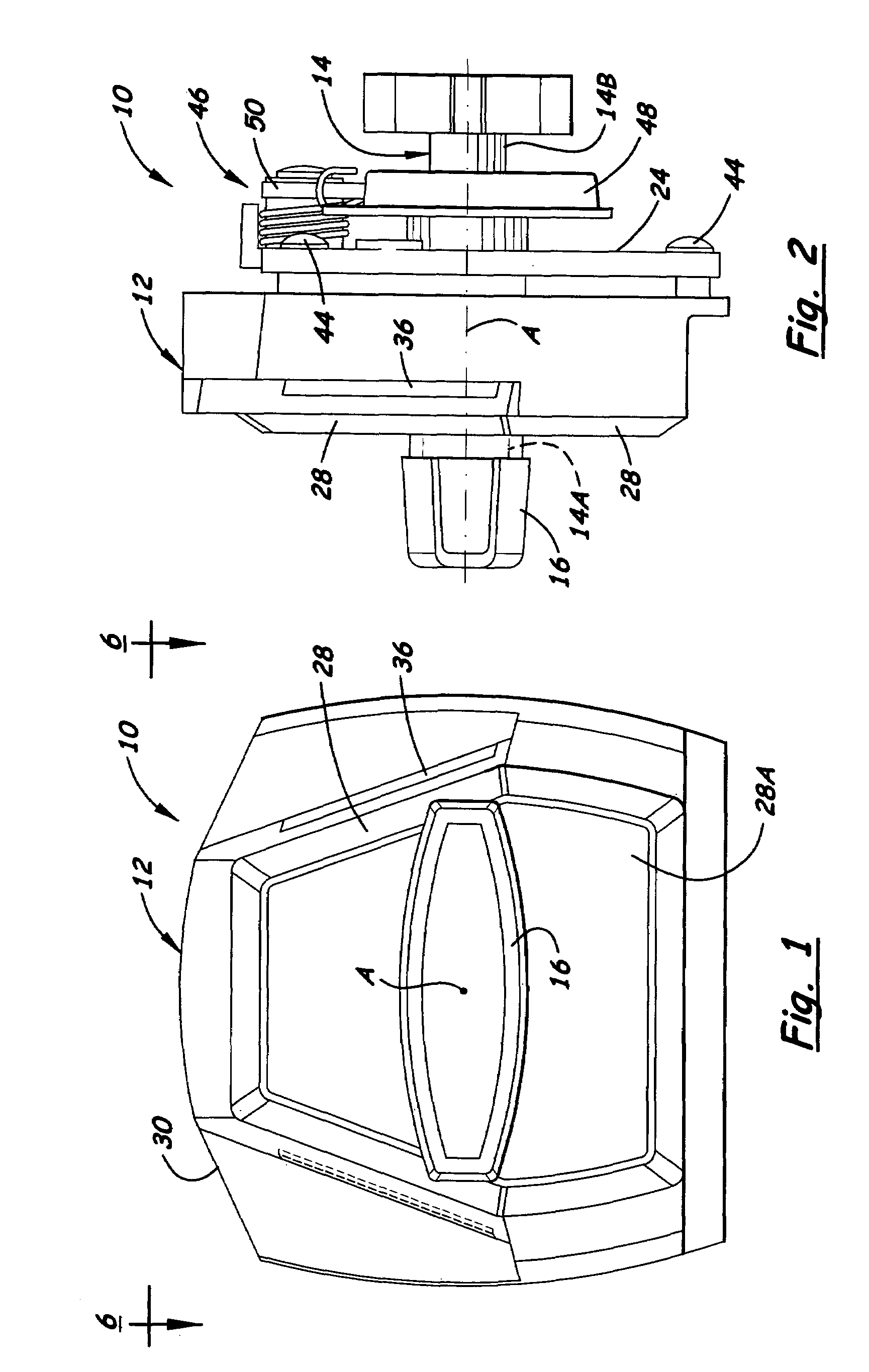
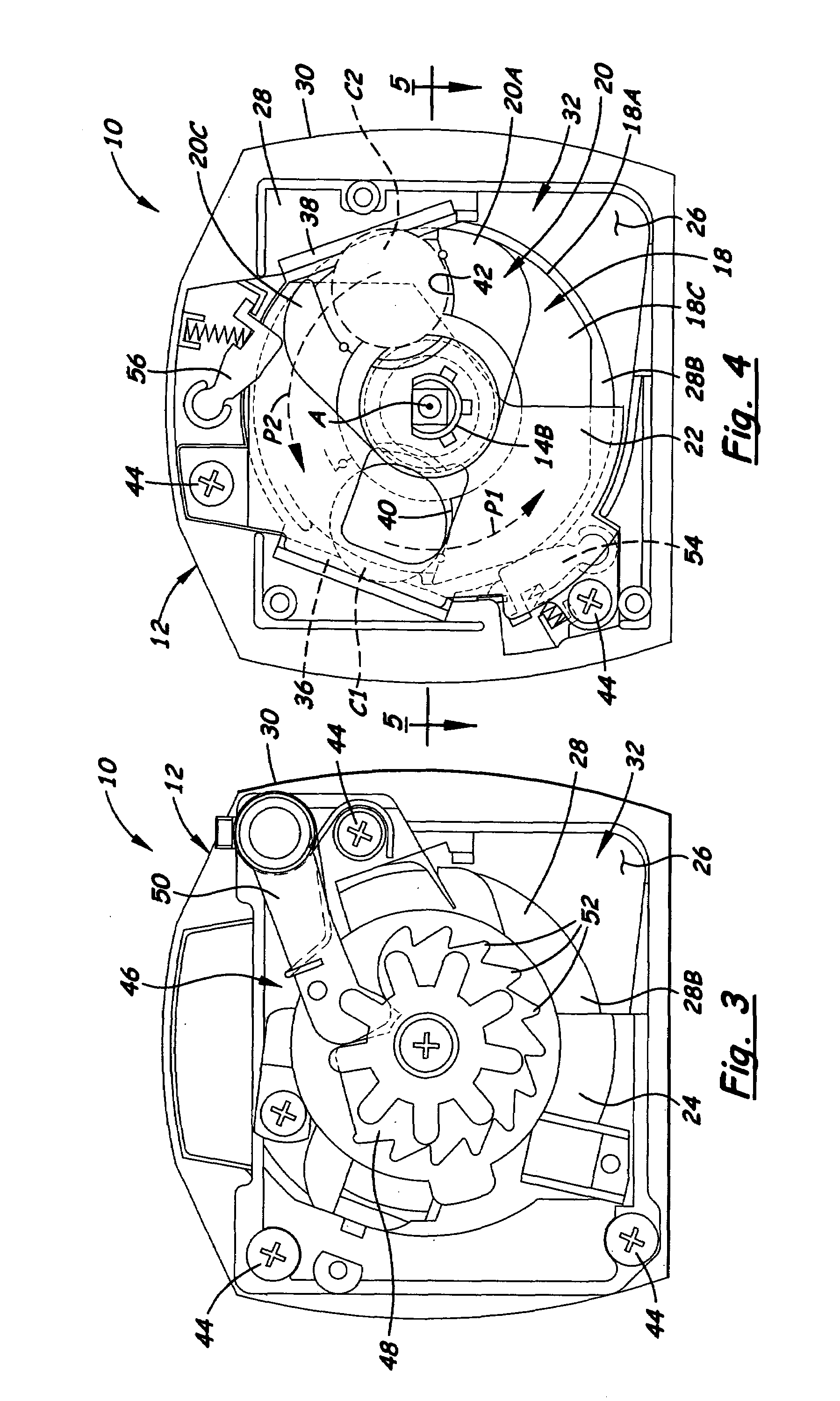
[0023]Referring to the drawings and particularly to FIGS. 1 to 5, there is illustrated a dual coin actuation mechanism, generally designated 10, of the present invention. The dual coin actuation mechanism 10 basically includes a face or cover plate 12, a central shaft 14, a transverse handle 16 attached to a front end 14A of the central shaft 14, first and second coin carrier wheels 18, 20, and first and second coin retainer plates 22, 24. At the outset, it should be understood that the terms “first” and “second” are used herein to identify elements at “leading” and “trailing” positions in relation to one another as they travel counterclockwise along respective separate paths P1, P2 about an axis A of the cover plate 12, as viewed in FIGS. 4 and 8-10, from initial coin-deposit home positions to a coin discharge location 26. Thus, for example, when viewed along the respective paths P1, P2, a first coin C1 is the leading coin by being closer to the coin discharge location 26 than is a...


PUM


Abstract

A dual coin mechanism for a vending machine includes a cover plate having a peripheral flange with first and second coin slots defined therein angularly and axially offset from one another about and along an axis defined by the cover plate, and first and second coin carrier wheels mounted for rotation about the axis relative to the cover plate and respectively having first and second coin recesses angularly and axially offset from one another about and along the axis. The axially offset relationships between the first and second slots, the first and second recesses and consequently first and second paths taken by first and second coins carried in the first and second recesses ensure that the first and second coins are not brought into alignment respectively with the second and first slots and thus are made inaccessible to a user during their travel along the first and second paths.

Description

BACKGROUND OF THE INVENTION[0001]1. Field of the Invention[0002]The present invention generally relates to a coin actuation mechanism for a coin-operated vending machine and, more particularly, is concerned with a dual coin actuation mechanism with angularly and axially offset coin slots and recesses.[0003]2. Description of the Prior Art[0004]U.S. Pat. Nos. 5,657,848 and 5,924,542 to Schwarzli and U.S. Pat. Appln. Pub. No. 2004 / 0206602 to Chang disclose prior art examples of dual-coin actuation mechanisms for a vending machine. Each of these prior art disclosures teaches a dual-coin actuation mechanism which has a front cover plate, a central shaft mounted through the cover plate for rotation about a central axis defined by the cover plate, a handle disposed adjacent to and exterior of the cover plate and rigidly connected to an outer end of the central shaft, and a coin carrier wheel mounted for rotation with the central shaft relative to the cover plate. The cover plate has first ...

Claims


Application Information

Patent Timeline
Patent Type & Authority Patents(United States)
IPC IPC(8): G07D3/00G07F11/00G07F13/00G07F15/00G07F17/00G07F5/00
CPCG07D5/02G07F5/04
Inventor CHANG, KIL JAE
Owner CHANG KIL JAE
Why Eureka
Try Eureka