
Coil sling

a technology of slings and coils, applied in the direction of load securing, transportation and packaging, transportation items, etc., can solve the problems of prolonged roadway closure and significant risk to life and property, and achieve the effect of relieving tension on the sling

Inactive Publication Date: 2007-09-18
JERNIGAN WILLIAM SCOTT
View PDF5 Cites 15 Cited by
  • Summary
  • Abstract
  • Description
  • Claims
  • Application Information

AI Technical Summary

Benefits of technology

[0005]The present invention is a safety coil sling for securing a coil on a flatbed trailer. The sling preferably comprises a round or elliptical primary cable attached at one end to a first anchoring chain and at an opposite end to a second anchoring chain, and a plurality of connecting cables for connecting opposite sides of the primary cable across the top of the coil, thereby securing the coil on the trailer. The first and second anchoring chains are anchored to the sides of the trailer. The sling preferably further comprises a third anchoring chain having a central portion coupled to one side of the primary cable and a fourth anchoring chain having a central portion coupled to an opposite side of the primary cable, wherein the ends of the third anchoring chain are anchored to the trailer forward of the coil and the ends of the fourth anchoring chain are anchored to the trailer rearward of the coil. In an alternate embodiment, the primary cable is divided into parallel segments at the points of attachment of the connecting cables and the connecting cables are slidably attached to one of the parallel segments to allow the connecting cables to slide within a fixed area, thus providing a mechanism for relieving tension on the sling during weight shifts within the coil occurring during transport.

Problems solved by technology

Because of their substantial weight, these coils sometimes break loose from the securing chains during transportation and fall off the flatbed trailer, potentially resulting in prolonged closure of roadways while the coil is lifted back onto a trailer and re-secured.
Further, there is a significant risk to life and property when these coils break loose due to their substantial weight.

Method used


Image

  • Coil sling
  • Coil sling
  • Coil sling

Examples


Embodiment Construction

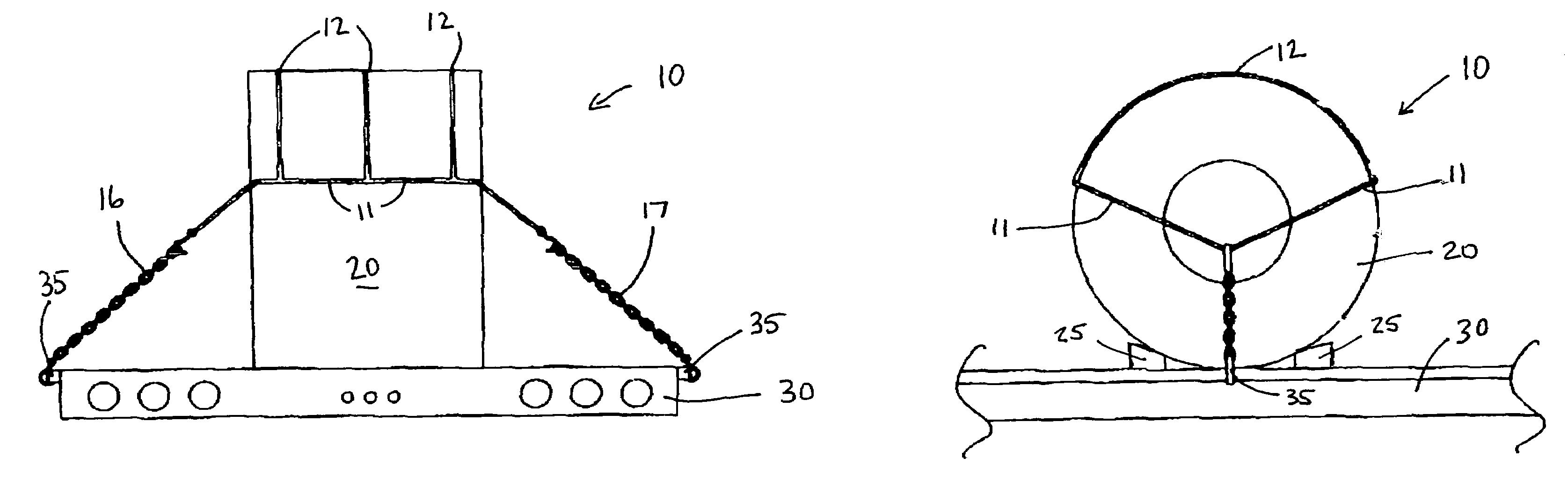
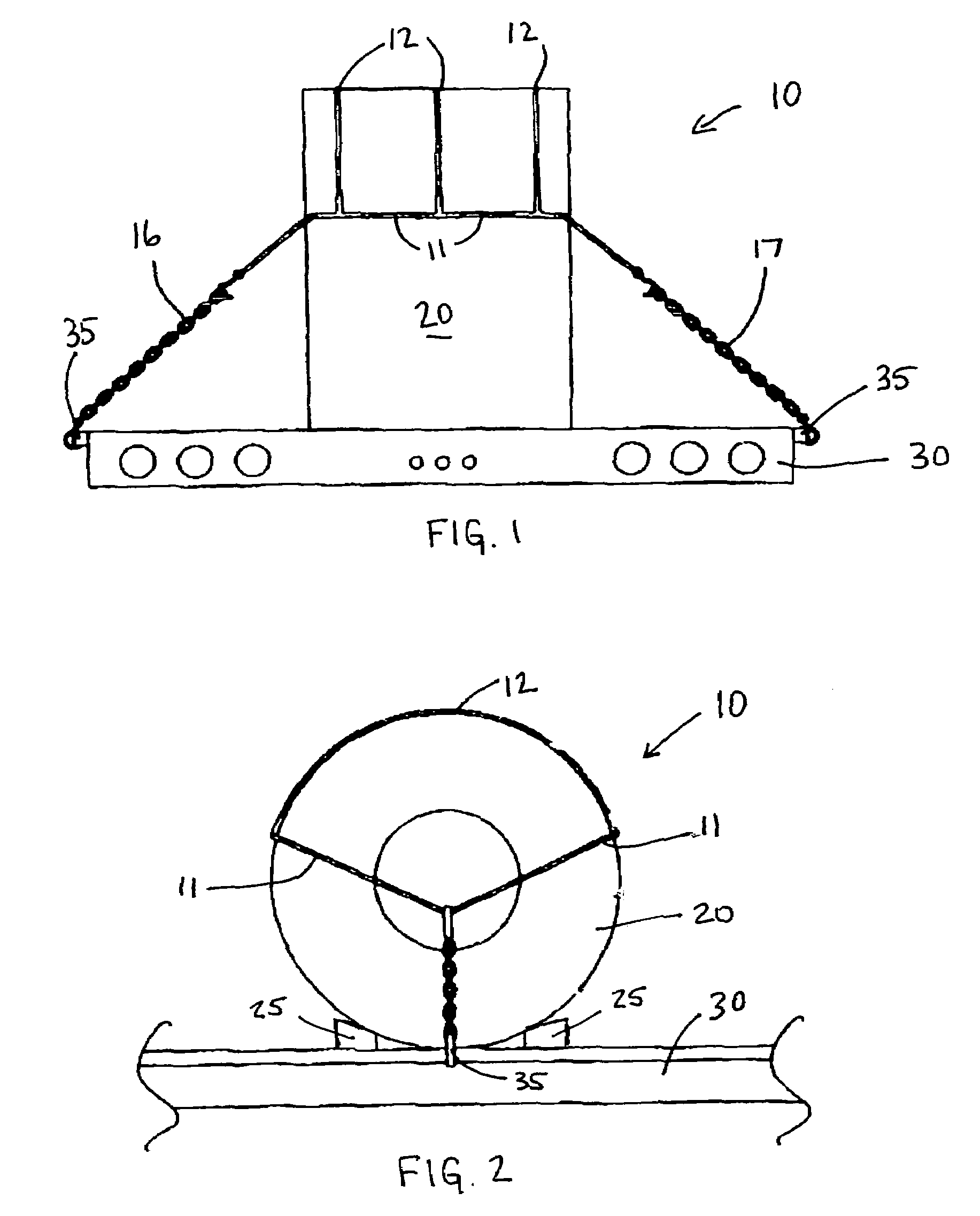
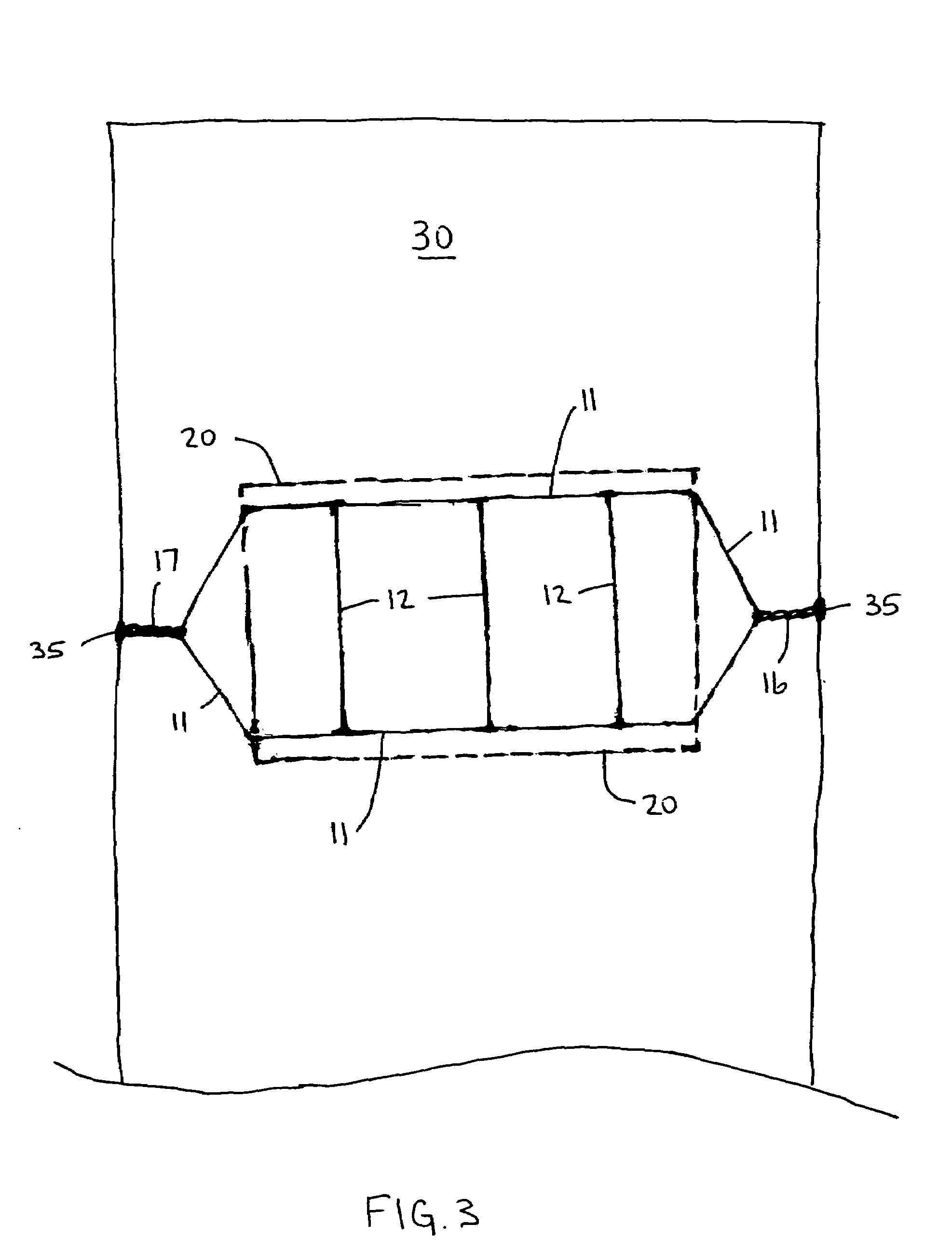
[0011]The present invention is a safety coil sling 10 for securing a coil 20 on a flatbed trailer 30. The sling 10 preferably comprises a closed round or elliptical primary cable 11 attached at one end to a first anchoring chain 16 and at an opposite end to a second anchoring chain 17, and a plurality of substantially parallel secondary cables 12 for connecting opposite sides of the primary cable 11 across the top of the coil 20, thereby securing the coil 20 on the trailer 30. The primary and secondary cables 11, 12 are preferably made of steel. The first and second anchoring chains 16, 17 are each anchored to an anchoring position 35 formed along the side of the trailer 30, as is known in the prior art. A coil rack 25 is preferably used to stabilize the coil 20 to prevent the coil 20 from tending to roll, as is known in the prior art.

[0012]The sling 10 preferably further comprises a third anchoring chain 18 having its ends anchored to the trailer 30 forward of the coil. The third a...


PUM


Abstract

A safety coil sling for securing an industrial metal coil on a flatbed trailer having a round or elliptical primary cable attached at one end to a first anchoring chain and at an opposite end to a second anchoring chain, and a plurality of connecting cables for connecting opposite sides of the primary cable across the top of the coil, thereby securing the coil on the trailer. In an alternate embodiment, the primary cable is divided into parallel segments at the points of attachment of the connecting cables and the connecting cables are slidably attached to one of the parallel segments to allow the connecting cables to slide within a fixed area, thus providing a mechanism for relieving tension on the sling during weight shifts within the coil occurring during transport.

Description

RELATED PATENT APPLICATION[0001]The present application claims priority to U.S. Provisional Patent Application No. 60 / 643,213, filed Jan. 12, 2005, incorporated herein by reference.FIELD OF THE INVENTION[0002]The present invention is related to cargo securing systems, and more particularly, to an apparatus for securing industrial metal coils on a flatbed trailer.BACKGROUND OF THE INVENTION[0003]Industrial metal coils are large sheets of metal formed into a donut-shaped coil that weigh as much as 30,000-50,000 lbs. These coils are presently transported on flatbed trailers and are typically secured by chains running through the center of the coil. Because of their substantial weight, these coils sometimes break loose from the securing chains during transportation and fall off the flatbed trailer, potentially resulting in prolonged closure of roadways while the coil is lifted back onto a trailer and re-secured. Further, there is a significant risk to life and property when these coils ...

Claims


Application Information

Patent Timeline
Patent Type & Authority Patents(United States)
IPC IPC(8): B60P7/08
CPCB60P7/12
Inventor JERNIGAN, WILLIAM SCOTT
Owner JERNIGAN WILLIAM SCOTT
Learn More