
Weight trainer with load detection system

a technology of load detection and weight trainer, applied in the field of fitness equipment, can solve the problems of not being able to calculate or count calories during fitness exercise, reed switch, and magnetic sensing method failing to ensure the maintenance of consistency in distance, etc., and achieve the effect of promoting fitness exercise efficiently

Inactive Publication Date: 2014-01-30
JOONG CHENN IND CO LTD
View PDF6 Cites 4 Cited by
  • Summary
  • Abstract
  • Description
  • Claims
  • Application Information

AI Technical Summary

Benefits of technology

The present invention is a weight trainer with a load detection system that helps users track their progress during fitness exercise. This helps users understand the effects of the exercise in real-time, which encourages them to work harder and more efficiently. The system is precise and can quantify the information gained during the exercise, providing a more detailed analysis of the results.

Problems solved by technology

However, the weight trainer has a fixed training goal and effect, but is not capable of counting or calculating calorie consumption during fitness exercise.
To evaluate the sports and fitness exercise taken by them, users have to record or read related fitness exercise data to the detriment of efficient promotion of fitness exercise.
However, the aforesaid magnetic sensing method fails to ensure the maintenance of consistency in the distance between the reed switch 94 and the selection tabs 96 due to a production tolerance of the selection tabs 96.
In addition, an error of the position of a fall of the selection tabs 96 is likely to cause the reed switch 94 to make a wrong judgment.
Accordingly, the detection status of the structure is relatively unstable.
In conclusion, the conventional fitness equipment has the aforesaid drawbacks and thus has room for improvement.

Method used


Image

  • Weight trainer with load detection system
  • Weight trainer with load detection system
  • Weight trainer with load detection system

Examples


Embodiment Construction

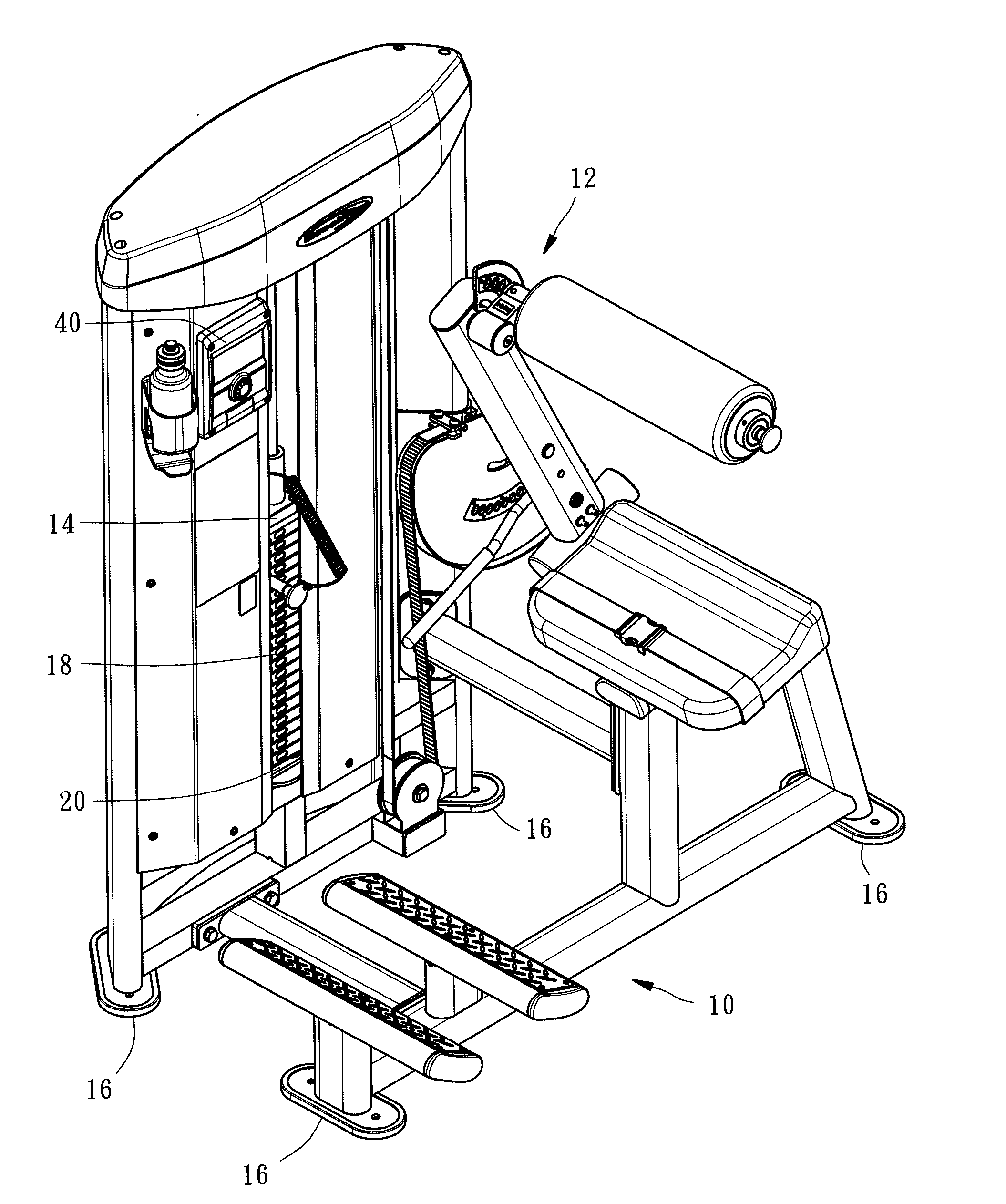
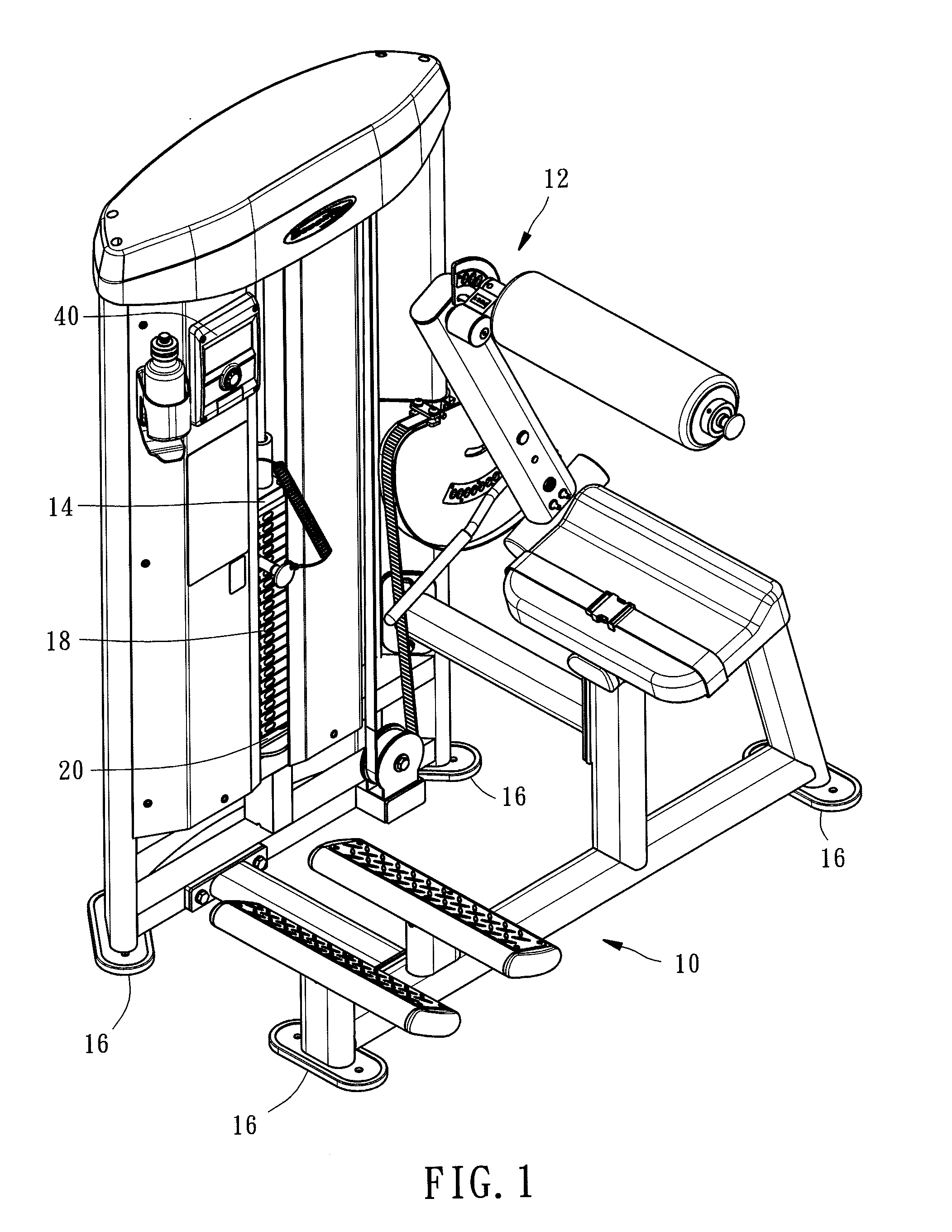
[0023]FIG. 1 is a perspective view of a weight trainer with a load detection system according to a preferred embodiment of the present invention.

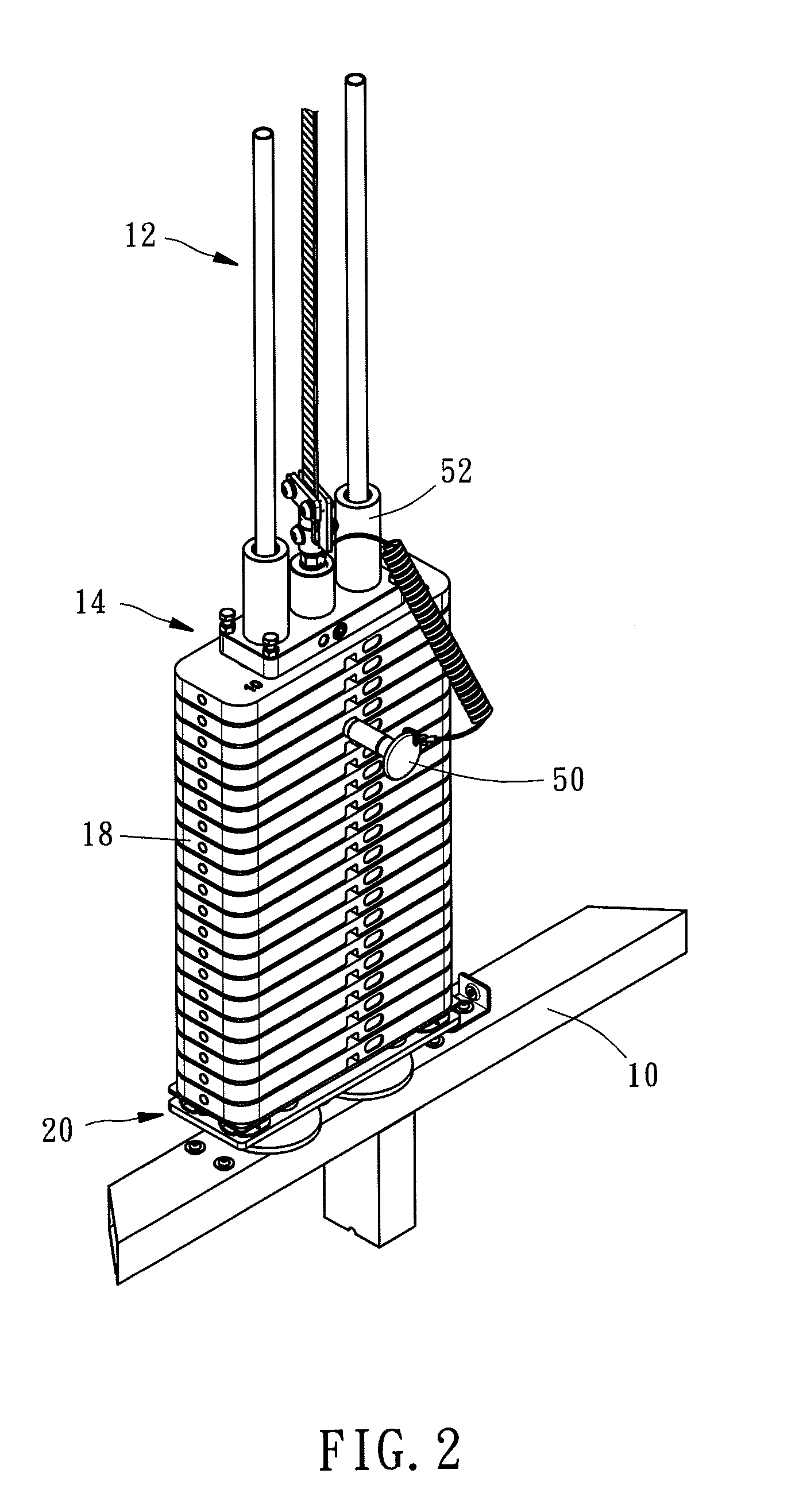
[0024]FIG. 2 is a schematic view of a portion of the weight trainer with a load detection system according to the preferred embodiment of the present invention, showing the weight allocating device which has not yet been pulled up.

[0025]FIG. 3 is a front view of a portion of the weight trainer with a load detection system according to the preferred embodiment of the present invention, showing that the selection tabs have been pulled up in part.

[0026]FIG. 4 is a perspective view of a load detecting device according to the preferred embodiment of the present invention.

[0027]FIG. 5 is an exploded view of the load detecting device according to the preferred embodiment of the present invention.

[0028]FIG. 6 is a cross-sectional view of the load detecting device according to the preferred embodiment of the present invention, showing relative posit...


PUM


Abstract

A weight trainer with a load detection system includes a frame, a load detecting device, and a display device. The frame has a transmission device, a weight allocating device, and a stand. The transmission device is disposed on one side of the frame. The weight allocating device is connected to the transmission device and can undergo displacement in the vertical direction of the stand. The load detecting device is disposed beneath the weight allocating device. The load detecting device includes a sensor, a base, and a platform. The sensor is abuttingly disposed between the base and the platform. The display device is electrically connected to the load detecting device. Accordingly, the weight trainer with a load detection system is effective in detecting a weight change precisely, enabling a user taking fitness exercise to gain access to information thereof in real time, and quantifying the information.

Description

BACKGROUND OF THE INVENTION[0001]1. Field of the Invention[0002]The present invention relates to fitness equipment, and more particularly, to a weight trainer with a load detection system.[0003]2. Description of Related Art[0004]At present, fitness equipment is in wide use, whereas a weight trainer is the commonest required fitness equipment of sports and fitness exercise.[0005]A typical weight trainer has a weight allocating device and at least a transmission device connected to the weight allocating device. The weight allocating device has a plurality of selection tabs adjustable by a user according to the weight required for muscle training and therefore capable of providing an appropriate weight load. However, the weight trainer has a fixed training goal and effect, but is not capable of counting or calculating calorie consumption during fitness exercise. To evaluate the sports and fitness exercise taken by them, users have to record or read related fitness exercise data to the ...

Claims


Application Information

Patent Timeline
Patent Type & Authority Applications(United States)
IPC IPC(8): A63B21/005
CPCA63B71/0622A63B23/0233A63B24/0062A63B2220/52G01G19/4146G01G19/52A63B21/0628A63B21/4033A63B21/4047
Inventor CHEN, JAMES
Owner JOONG CHENN IND CO LTD
Learn More