Modular CPAP compressor

a compressor and module technology, applied in machines/engines, liquid fuel engines, positive displacement liquid engines, etc., can solve the problems of increasing the overall cost of cpap devices, and achieve the effects of reducing the operating efficiency of the compressor assembly, minimizing aerodynamic losses, and small air gap

Inactive Publication Date: 2008-12-18
CAREFUSION
View PDF18 Cites 28 Cited by
  • Summary
  • Abstract
  • Description
  • Claims
  • Application Information

AI Technical Summary

Benefits of technology

[0015]The impeller preferably includes a plurality of upwardly extending vanes each having a free edge defining a relatively small air gap with the housing interior surface. The impeller and bearing assembly are preferably sized and configured such that the air gap is maintained at a minimum (e.g., less than approximately 0.006 inches) during rotation of the impeller. In this manner, the compressor assembly minimizes aerodynamic losses such as vane-to-vane losses or losses resulting from parasitic fluid eddies which can reduce the operating efficiency of the compressor assembly.

Problems solved by technology

As may be appreciated, the need to design, test and manufacture completely different configurations of compressor assemblies for different patients having differing flow requirements substantially increases the overall cost of CPAP devices.

Method used


Image

  • Modular CPAP compressor
  • Modular CPAP compressor
  • Modular CPAP compressor

Examples


Embodiment Construction

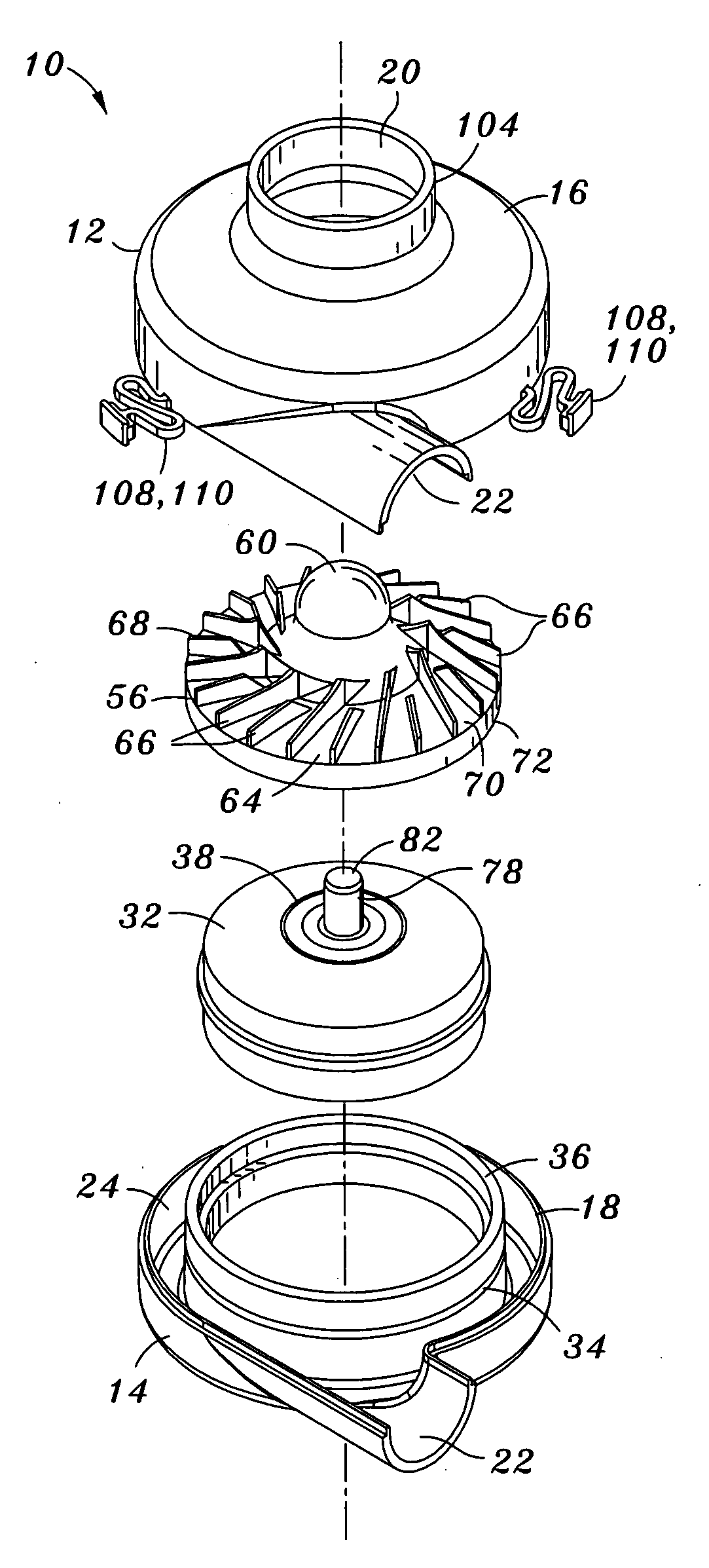
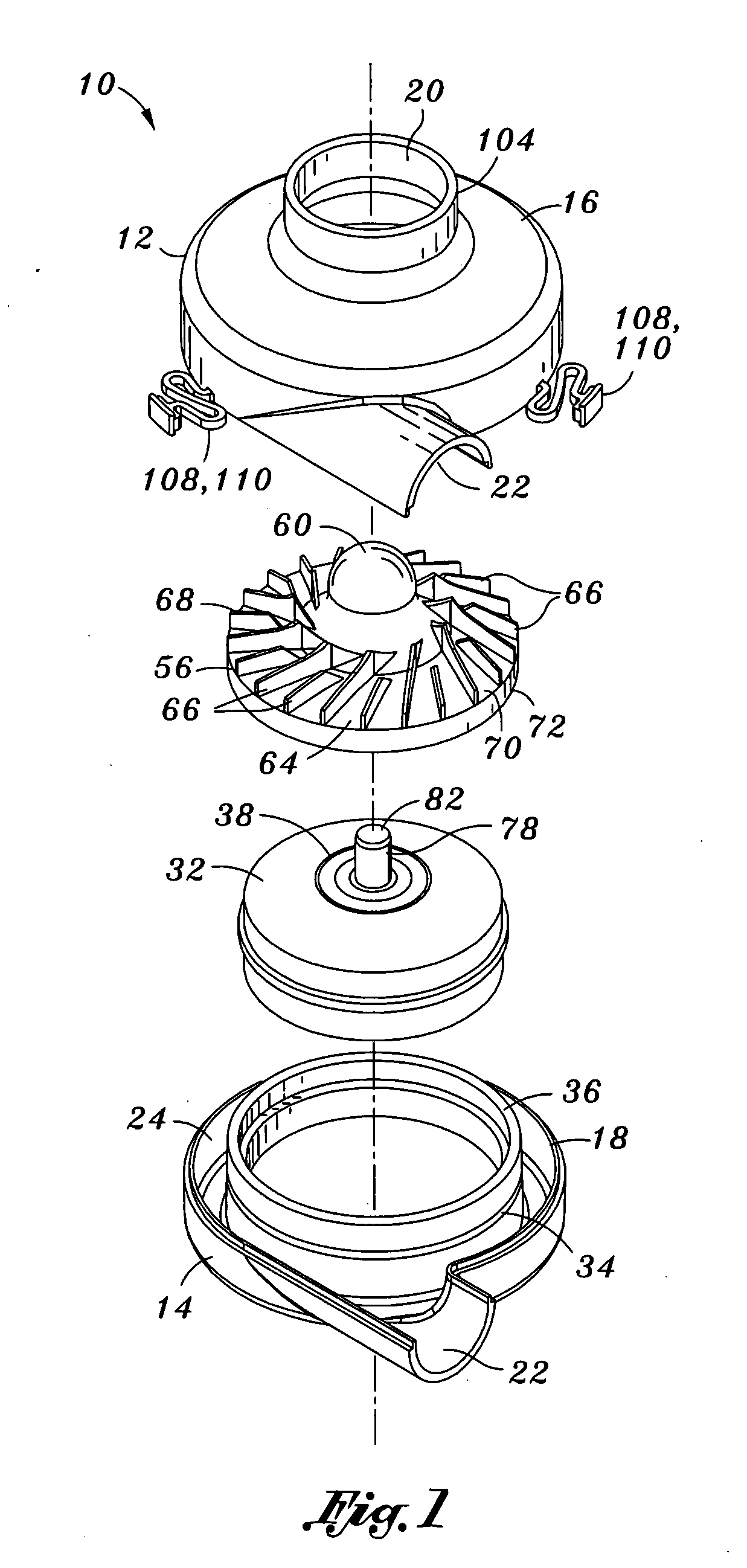
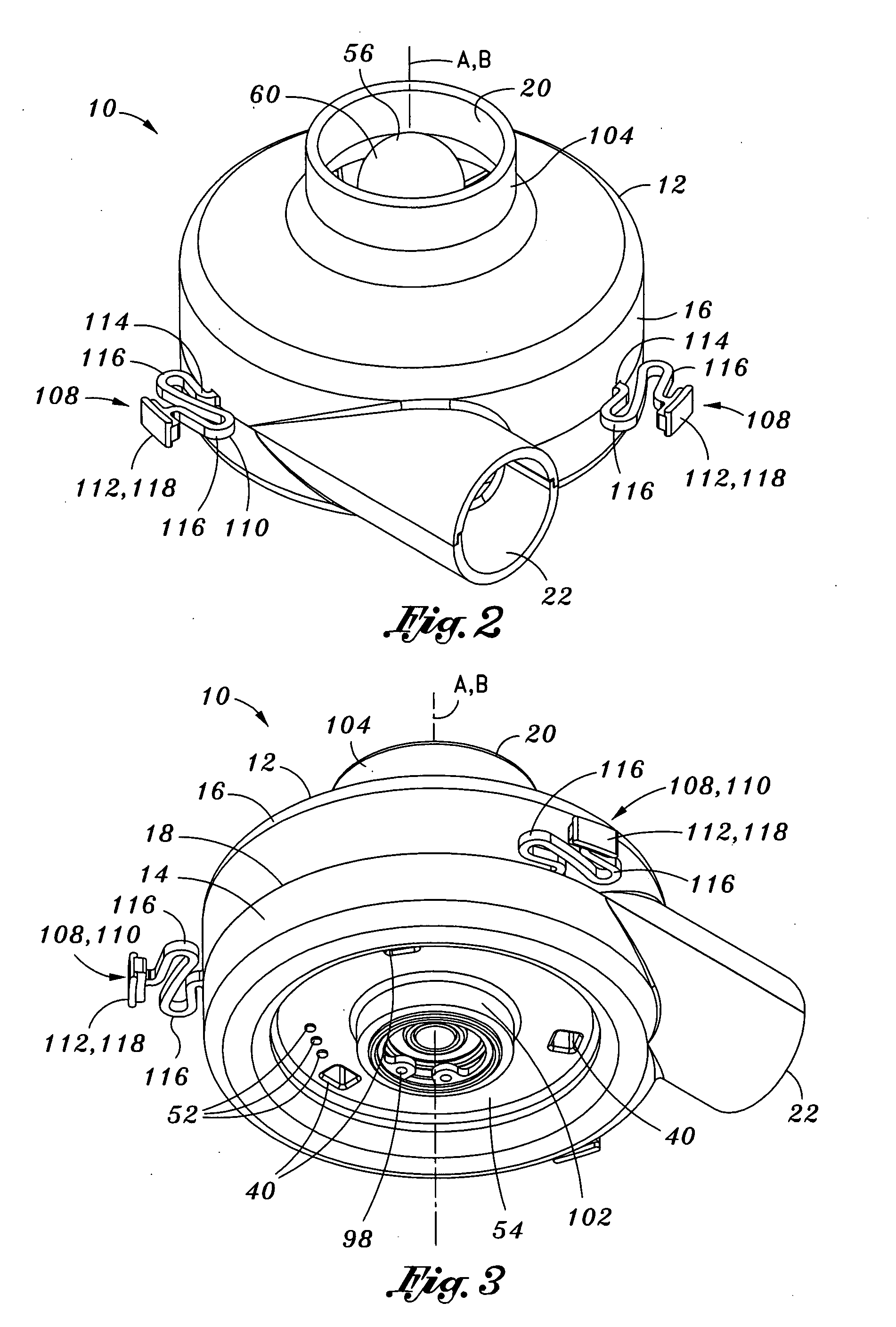
[0023]Referring now to the drawings wherein the showings are for purposes of illustrating preferred embodiments of the present invention and not for purposes of limiting the same, shown in FIGS. 1 to 6 is a modular compressor assembly 10 which, in its broadest sense, comprises a baseline or common motor assembly 30 configured to be engageable to blower housings 12 of differing geometry to achieve differing flow characteristics using the same common motor assembly 30. Toward this end, the compressor assembly 10 includes an engagement mechanism 128 to allow for mounting of the motor assembly 30 to the blower housings 12.

[0024]In this manner, the compressor assembly 10 may be economically manufactured and capable of producing a broad range of flow characteristics (i.e., different flow rates and pressures) for specific patient applications at a substantially reduced cost. Advantageously, the common motor assembly 30 may include oversized bearings in order to maintain the operating effic...


PUM

PropertyMeasurementUnit
perimeteraaaaaaaaaa
circumferenceaaaaaaaaaa
heightaaaaaaaaaa

Abstract

A modular compressor assembly comprises a common motor assembly, an impeller, a blower housing and an engagement mechanism. The common motor assembly includes a stator housing containing a stator assembly and having a rotor magnet rotatably disposed therewithin. The impeller is mounted to and rotatable with the rotor magnet. The blower housing is selectable from among a plurality of blower housings each having a different cross-sectional geometry. The engagement mechanism is formed on the stator housing and/or the blower housing and allows interchangeable mounting of different blower housing configurations to the common motor assembly in order to achieve varying flow characteristics of the compressor assembly.

Description

CROSS-REFERENCE TO RELATED APPLICATIONS[0001](Not Applicable)STATEMENT RE: FEDERALLY SPONSORED RESEARCH / DEVELOPMENT[0002](Not Applicable)BACKGROUND[0003]The present invention relates generally to patient ventilation systems and, more particularly, to a modular compressor assembly which can be assembled using a baseline or common motor assembly to which can be mounted various sizes and configurations of blower housings in order to achieve different flow capabilities for the compressor assembly.[0004]Blowers are commonly used in mechanical ventilators to generate compressed air for delivery to a patient. Such blower assemblies may comprise a blower housing having a blower inlet and a blower outlet. The blower assembly includes a motor assembly mounted within the blower housing and which is coupled to an impeller which draws air into the blower inlet. The air is compressed as it flows through the impeller and enters an annular chamber or volute after which the air is discharged from th...

Claims


Application Information

Patent Timeline
Patent Type & Authority Applications(United States)
IPC IPC(8): F04B17/03B23P15/00F04D29/40
CPCA61M16/0063A61M2207/00A61M16/0066Y10T29/49012F04D29/40Y10T29/49243
Inventor HOFFMAN, LESLIE
Owner CAREFUSION
Why Eureka
Try Eureka