Electric motor having an iron-free winding

a technology of electric motors and windings, which is applied in the direction of windings, magnetic circuit rotating parts, magnetic circuit shapes/forms/construction, etc., can solve the problems of increased ohmic losses, eddy current losses, and relatively high manufacturing costs of laminated stators, etc., to achieve low cost, small winding material, and low electric resistance of electric motors according to the invention

Active Publication Date: 2017-06-20
PATENTVERWGESELLSCHAFT PALIBA GMBH
View PDF48 Cites 4 Cited by
  • Summary
  • Abstract
  • Description
  • Claims
  • Application Information

AI Technical Summary

Benefits of technology

[0062]The electrical resistance of the electric motor according to the invention is relatively low because the air gap winding has relatively large cross-sections, and overall relatively little winding material is required. Furthermore, relatively short electrical connecting conductors are used between the individual windings of the phases. Due to thin-wall cylindrical ring of the stator, the core losses are lower than in conventional motors, because less iron material is required to produce the cylindrical ring.
[0063]The electric motor according to the invention, which is characterized by relatively short winding connections, for example in meander pattern, and a relatively small remaining air gap, has relatively low hysteresis losses, eddy current losses and ohmic losses.
[0064]The electric motor according to the invention is also characterized by a very low weight combined with a relatively high power density and is very easy to produce, wherein the dimensions of the primary part, the secondary part, the winding arrangement and the magnet poles can be readily changed.

Problems solved by technology

Losses occur during this energy conversion, which are essentially composed of ohmic losses, eddy current losses, hysteresis losses and friction losses.
The use of a high number of turns enables high power output, however at the expense of increased ohmic losses.
Since the magnetic field in the windings of the electric motor varies over time, eddy current losses occur in the form of heat, which is dissipated in the iron parts of the motor.
The manufacture of these laminated stators is relatively expensive and these stators are not always offered by the various manufacturers.
In addition, permanent-magnet electric motors are increasingly produced which, however, are unsuited for asynchronous motors.

Method used


Image

  • Electric motor having an iron-free winding
  • Electric motor having an iron-free winding
  • Electric motor having an iron-free winding

Examples


Embodiment Construction

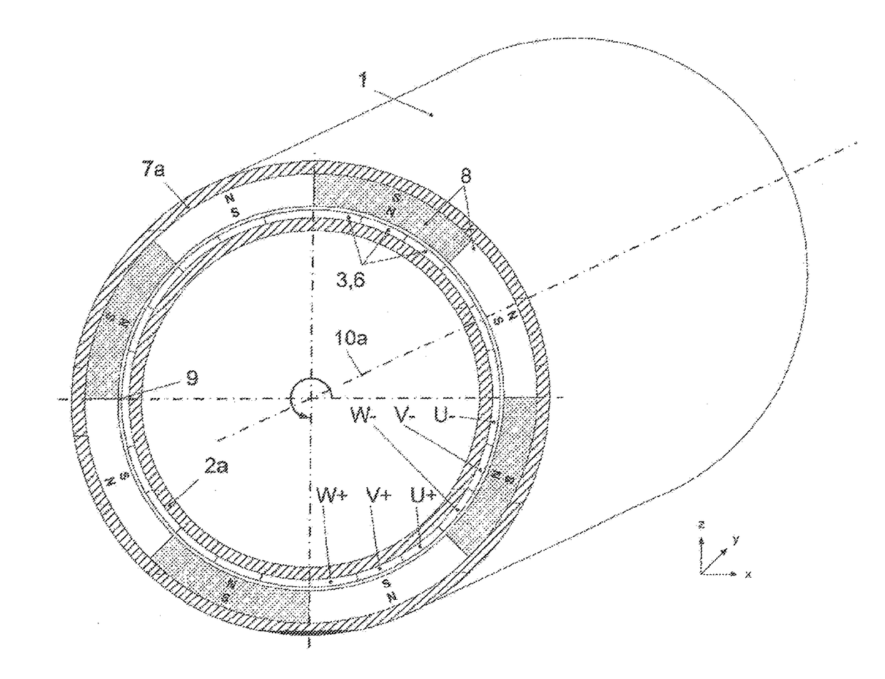
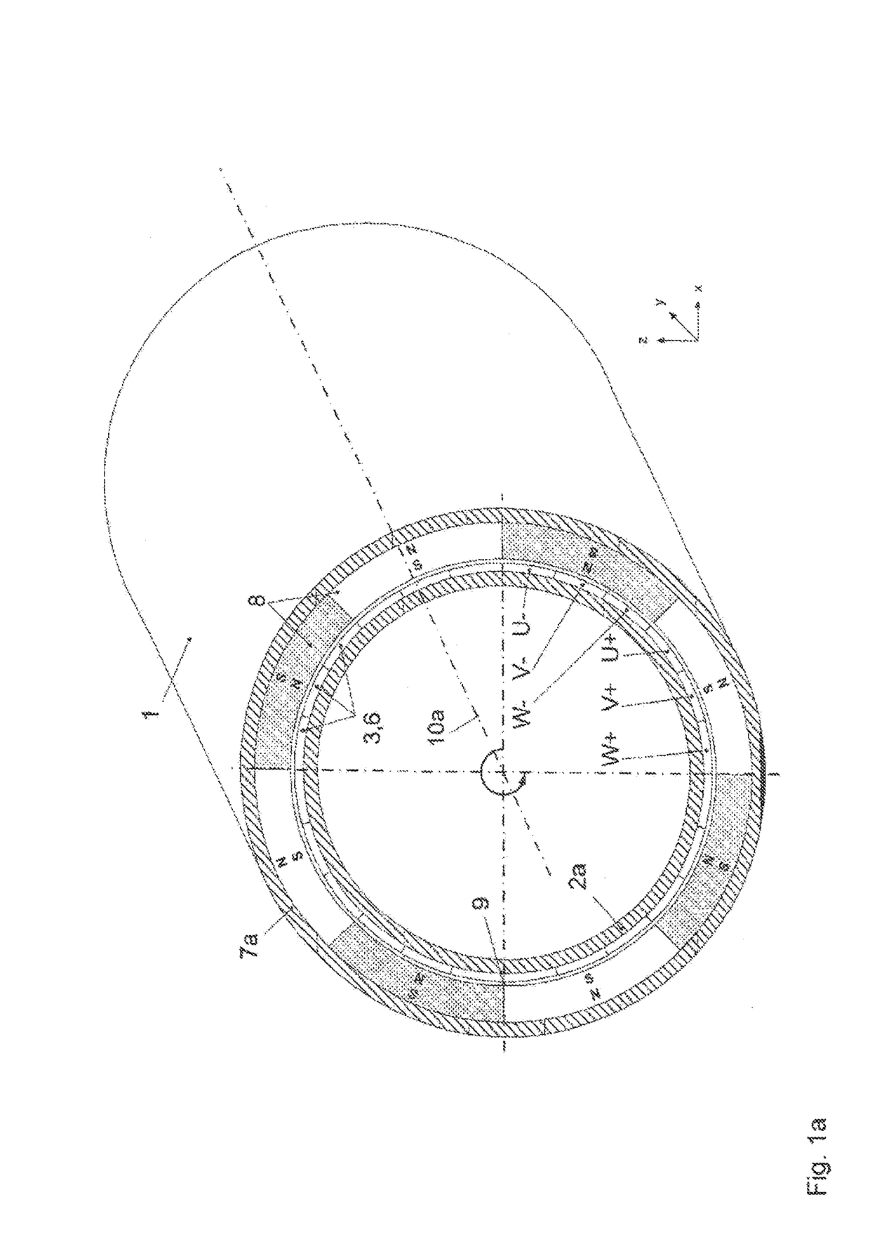
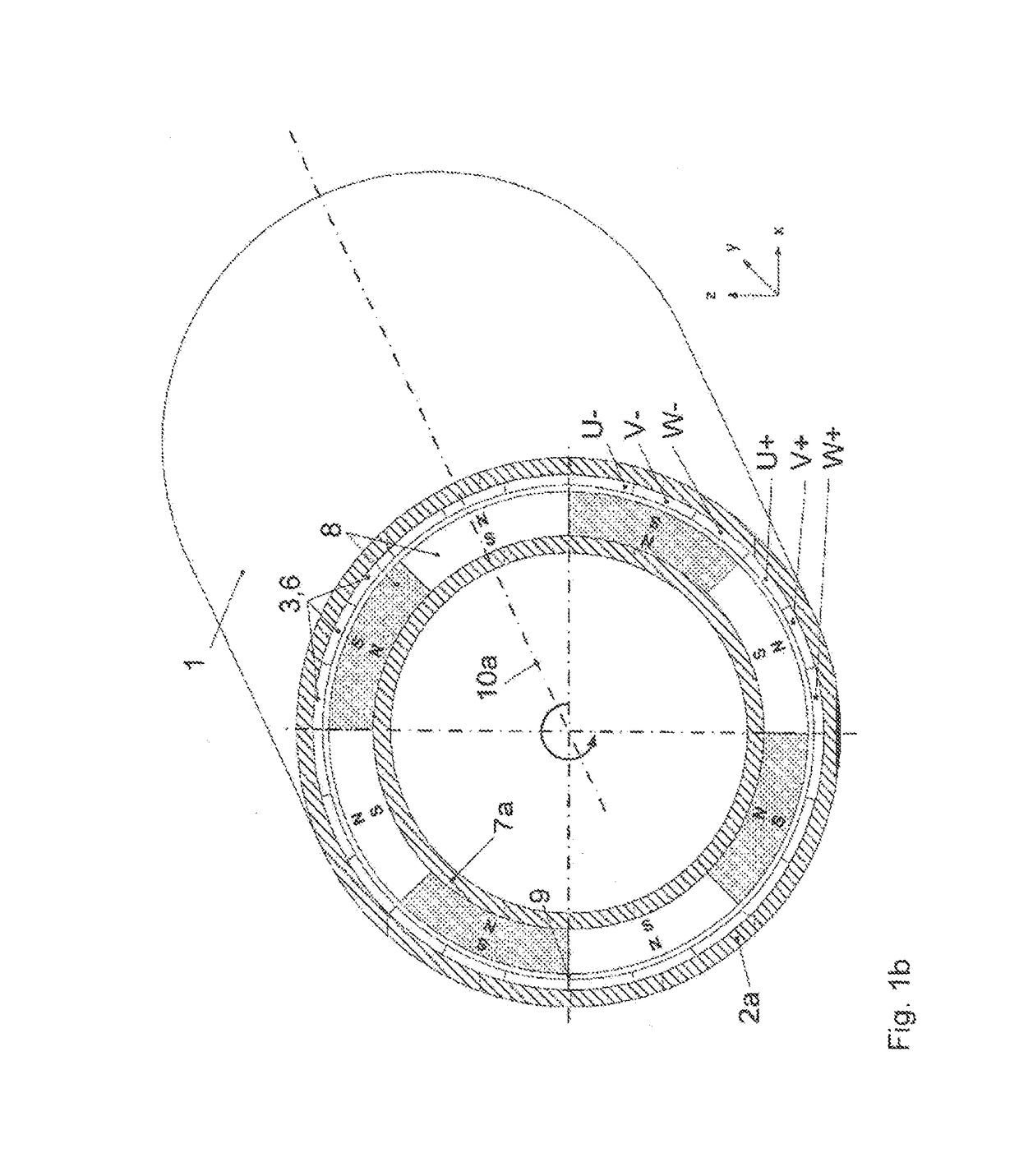
[0075]FIG. 1a shows schematically the structure of an electric motor 1 with an external rotor, i.e. the primary part 2a and the winding arrangement 3 are located inside the secondary part 7a with the magnetic poles 8. The winding arrangement 3 is here composed of three phases 6, designated with the letters “U”, “V” and “W”, wherein a phase is composed of several phase windings 4 and electrical connection elements 5 which, although not illustrated in FIG. 1a, are visible in FIG. 2, wherein at least one phase winding 4 of a phase 6 is located underneath a magnetic pole 8 in the air gap 9, in particular in such a way that the phase windings 4 are oriented parallel to the rotation axis 10a, which implies that all magnetic poles 8 are used at all times for torque formation. The magnetic poles 8 are polarized radially in relation to the rotation axis 10a, with the polarization alternatingly changing between the adjacent magnetic poles 8. The primary part 2a and the secondary part 7a are s...


PUM


Abstract

An electric motor (1), comprising a primary part (2a, 2b) having an iron-free winding device (3) that comprises at least two phases (6), wherein one phase (6) comprises at least two phase windings (4) and at least one electrical connecting element (5), a secondary part (7a, 7b) having an even number of magnetic poles (8), which are arranged alternatively on the secondary part (7a, 7b), wherein the winding device (3) is arranged in an air gap (9) between the primary part (2a, 2b) and the secondary part (7a, 7b) relative to an axis (10a, 10b), in such a manner that each phase winding (4) of a phase (6) is arranged opposite a respective magnetic pole (8) and all magnetic poles (8) are usable simultaneously for force formation.

Description

[0001]This is an application filed under 35 USC §371 of PCT / DE2012 / 000140, filed on Feb. 16, 2012, claiming priority to DE 10 2011 111 352.9 filed on Aug. 29, 2011.BACKGROUND OF THE INVENTION[0002](1) Field of the Invention[0003]The invention relates to an electric motor having an ironless winding with externally or permanently excitable magnetic poles.[0004](2) Description of Related Art[0005]Electric motors are used more and more frequently in many applications. The electro-mechanical energy in such motor is converted either with permanent excitation using permanent magnets or with external excitation using two separate coil arrangements in the rotor and stator, as disclosed for example in DE 69 735 825 T2. Losses occur during this energy conversion, which are essentially composed of ohmic losses, eddy current losses, hysteresis losses and friction losses.[0006]The use of a high number of turns enables high power output, however at the expense of increased ohmic losses. The more w...

Claims


Application Information

Patent Timeline
Patent Type & Authority Patents(United States)
IPC IPC(8): H02K3/28H02K21/14H02K41/03H02K3/47H02K23/32H02K1/27H02K21/22
CPCH02K3/28H02K1/274H02K3/47H02K21/14H02K23/32H02K41/031H02K21/22
Inventor KASPER, ROLANDHEINEMANN, WOLFGANGBORCHARDT, NORMAN
Owner PATENTVERWGESELLSCHAFT PALIBA GMBH
Why Eureka
Try Eureka