Screw tip and molding system apparatus

a technology of molding system and screw tip, which is applied in the field of screw tip, can solve the problems of stress and wear of the check valve, deformation of the melt, and easy wear of the outside surface of the check valve and the inside surface of the opening surrounding the threaded bolt in the non-return valve, so as to simplify the machining of the screw tip head, the effect of simple manufacturing and assembly

Inactive Publication Date: 2007-09-18
HUSKY INJECTION MOLDING SYST LTD
View PDF12 Cites 1 Cited by
  • Summary
  • Abstract
  • Description
  • Claims
  • Application Information

AI Technical Summary

Benefits of technology

[0007]The present invention has many advantages. The check valve is simpler to manufacture and assemble within the check valve chamber. Movement of the check valve between the flow position and the flow cut off position is damped due to a melt of material, in operation, behind the check valve and in the narrow flow channels of the entry ports. The three pin support of the check valve is simpler to manufacture and assemble in the screw tip head. Machining of the screw tip head is simplified. The screw tip is capable of better withstanding shock energy during injection. Wear between the check valve and the barrel is reduced.
[0013]In an embodiment of the invention, the translatable member includes a sealing surface and the check valve chamber includes a sealing surface. In the shut off position, the sealing surface of the translatable member engages the sealing surface of the check valve chamber preventing, in use, a flow of material.

Problems solved by technology

There are a number of problems with the prior art device.
The flow path also includes a number of areas that trap melt which in turn leads to degradation of the melt.
The screw is supported by the peripheral edge of the check valve and diffuser engaging the inside cylindrical wall of the barrel causing stress and wear of the check valve.
The outside surface of the check valve and inside surface of the opening surrounding the threaded bolt in the non-return valve are prone to wear.

Method used


Image

  • Screw tip and molding system apparatus
  • Screw tip and molding system apparatus
  • Screw tip and molding system apparatus

Examples


Embodiment Construction

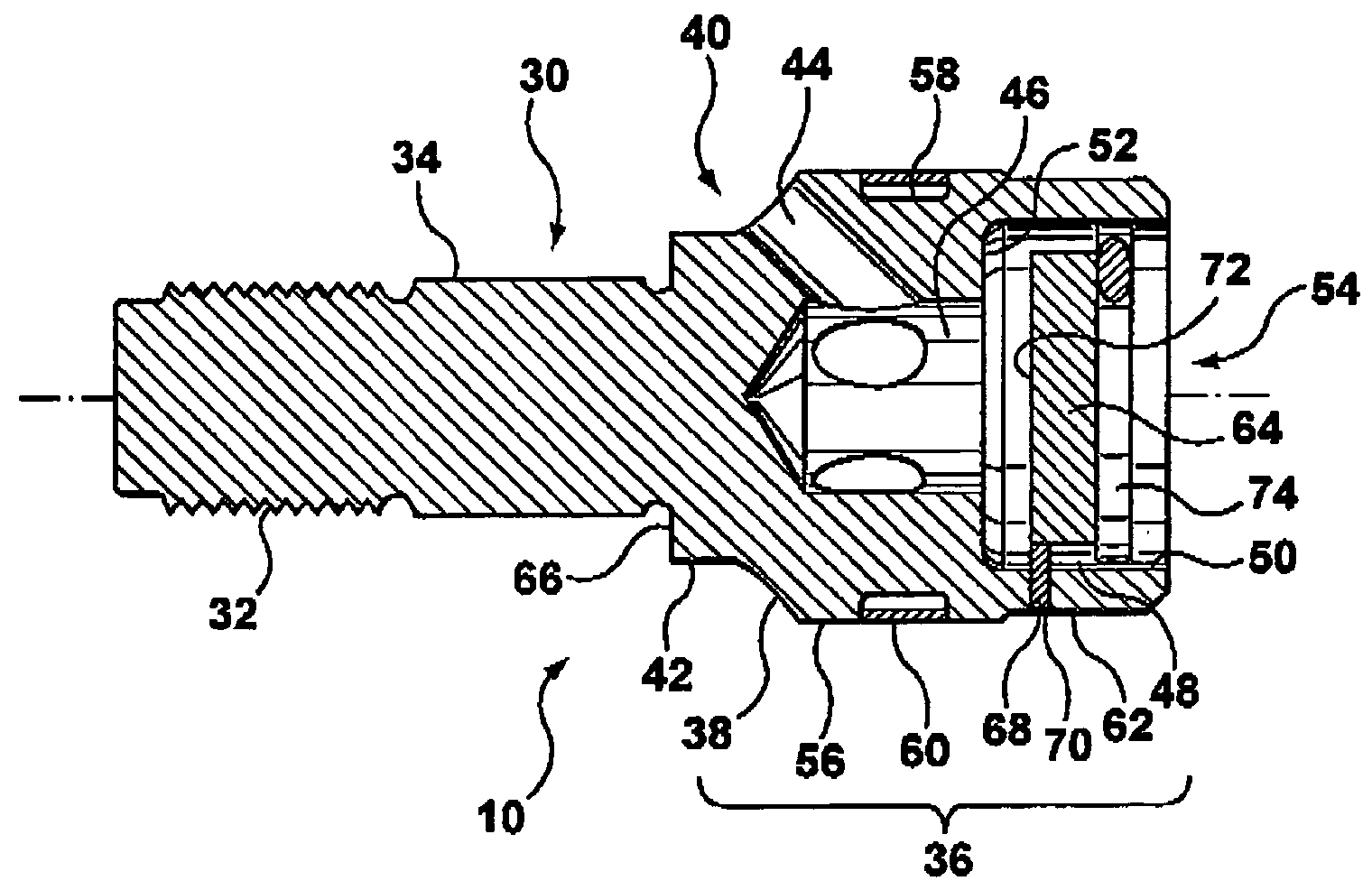
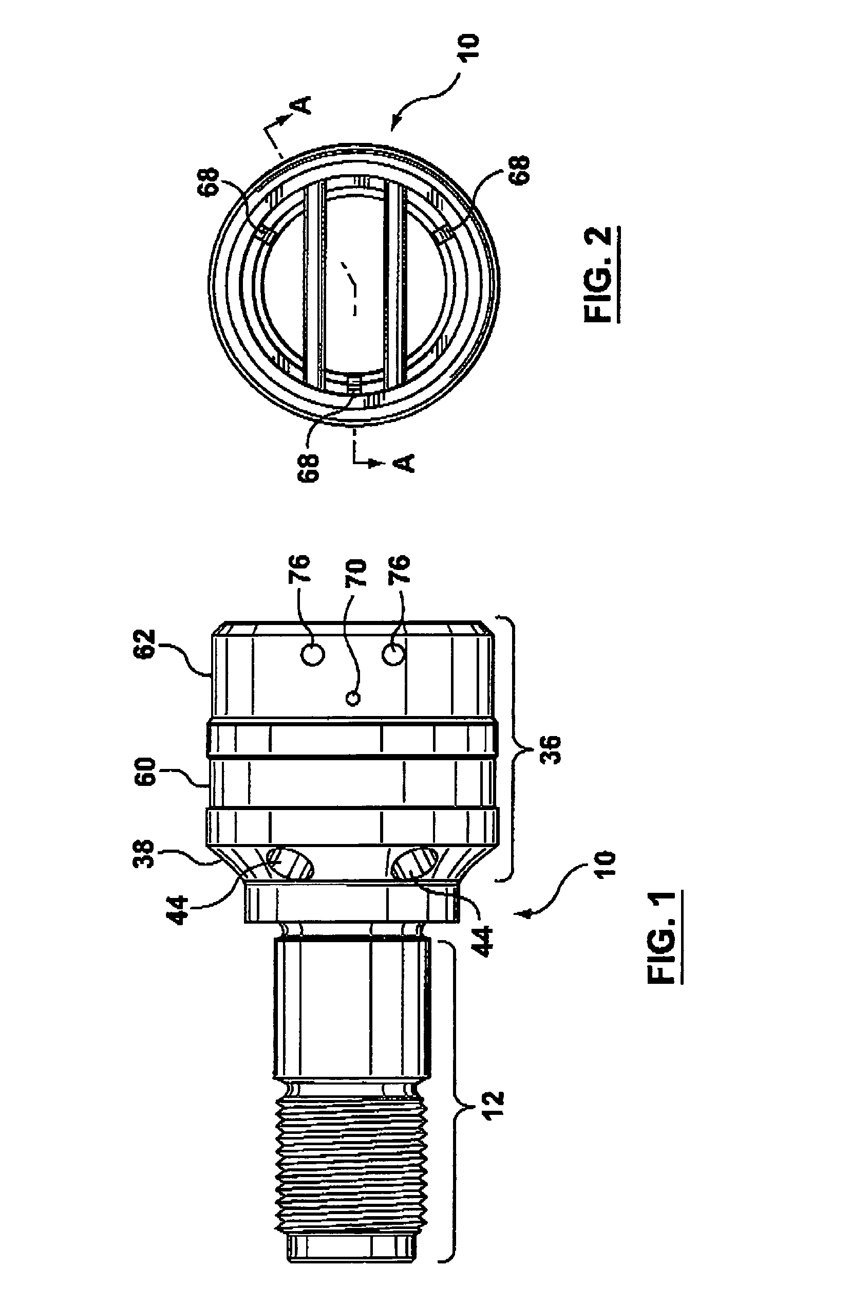
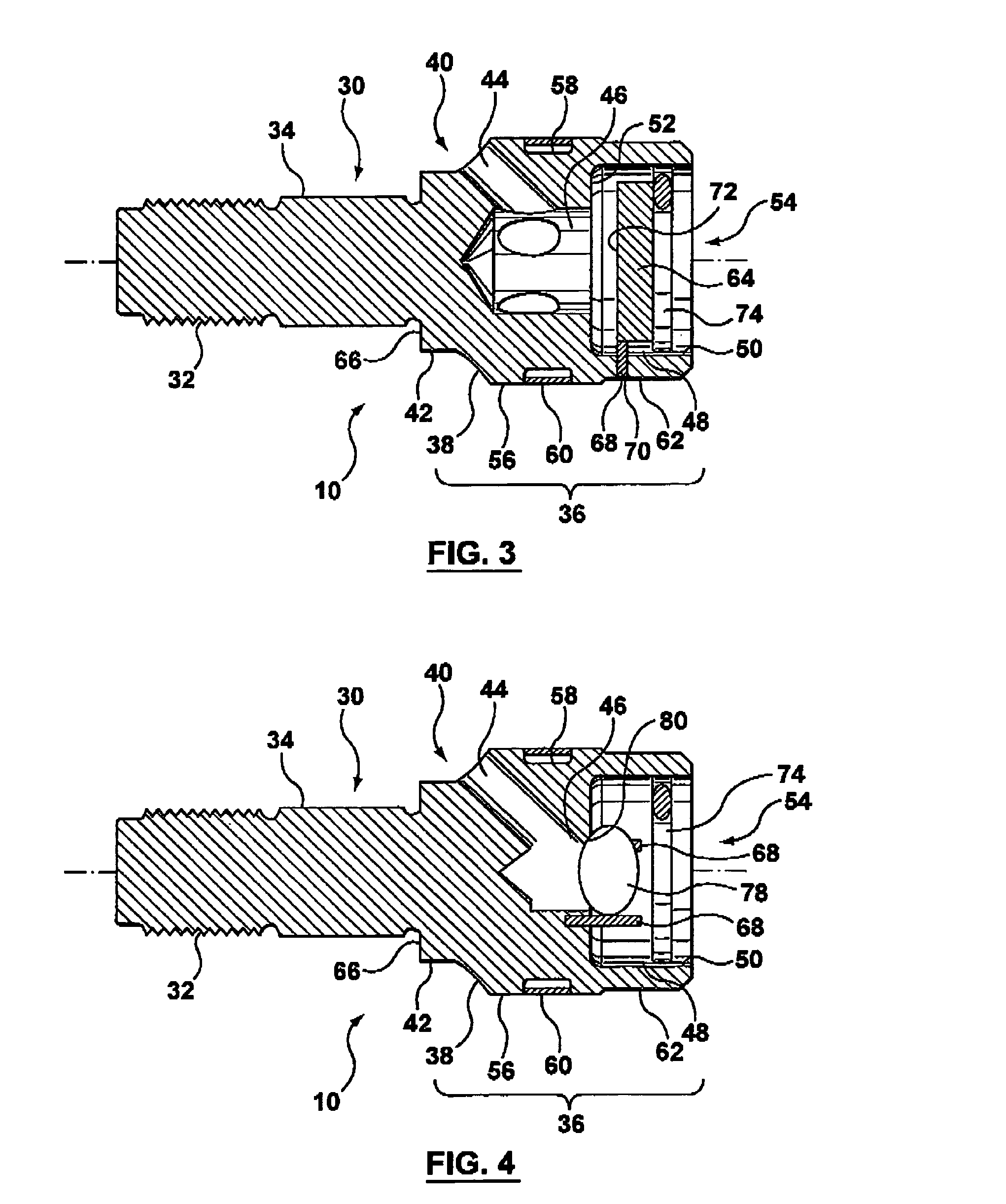
[0029]The present invention is described in accordance with an embodiment as illustrated with reference to FIGS. 1 and 2. A screw tip is illustrated generally at 10. The screw tip 10 includes a connection 12 section and a screw tip head 36 section. The connection 12 is for mounting and retaining the screw tip 10 with a screw (not shown). The screw tip head 36 houses the entry port 44 (or entry ports), central accumulator chamber 46, and check valve chamber 48 (see FIG. 3). The screw tip head 36 also houses a check valve 64 upon assembly.

[0030]The connection 12 and the screw tip head 36 of the invention are further described with reference to the cross sectional view illustrated in FIG. 3 which is taken along the line A-A of FIG. 2. The connection 12 has a substantially cylindrical body. The connection 12 has an engagement member 32, for example threads formed about a diameter of a cylindrical end. The engagement member 32 cooperates with complimentary threads in a cylindrical bore l...


PUM

PropertyMeasurementUnit
angleaaaaaaaaaa
circumferenceaaaaaaaaaa
stressaaaaaaaaaa

Abstract

A screw tip for use in a molding system apparatus is disclosed. The screw tip includes a connection section and screw tip head section. The screw tip head houses an entry port, or entry ports, an accumulation chamber, and a check valve chamber. A check valve is provided when assembled with the screw tip. The check valve may be a cylindrical plate or a spherical member or a conical member.

Description

BACKGROUND OF INVENTION[0001]1. Field of the Invention[0002]The present invention is directed to a screw tip, and more particularly to a screw tip for controlling the flow of a melt of material in a barrel of a molding system apparatus. For example, the molding system apparatus may be for a plastic injection molding system, or a metal injection molding system for molding a metal in a thixotropic state, or a die casting molding system.[0003]2. Background Information[0004]Screw tip assemblies forming a check valve mounted on the end of a screw are known in the art. For example, U.S. Pat. No. 2,885,734 issued to Wucher on May 12, 1959. The specification illustrates a two part check valve. A diffuser head is formed by a circular disk member that is mounted into an end of a screw. The disk includes a plurality of semi-circular openings around the peripheral edge of the disk. Portions of the disk intermediate the semi-circular openings extend outwardly and engage a inside cylindrical wall...

Claims


Application Information

Patent Timeline
Patent Type & Authority Patents(United States)
IPC IPC(8): B29C39/24B22D17/20B29C45/03B29C45/47B29C45/52B29C45/60
CPCB22D17/2061B29C45/52B29C45/60B29C45/03B29C45/47
Inventor ILMONEN, ROBERT
Owner HUSKY INJECTION MOLDING SYST LTD
Why Eureka
Try Eureka