Wideband apochromatic lens system

a wideband, apochromatic technology, applied in the field of optics, can solve the problems of complex lens assembly, high cost, color fringes at the edges of projected images, and high susceptibility to glass obsolescen

Active Publication Date: 2007-09-18
BAE SYST INFORMATION & ELECTRONICS SYST INTERGRATION INC
View PDF4 Cites 19 Cited by
  • Summary
  • Abstract
  • Description
  • Claims
  • Application Information

AI Technical Summary

Problems solved by technology

Without such compensation, the focal length of the system would change undesirably with the light spectrum received from the object, yielding axial chromatic aberration which causes color fringes to appear at the edges of the projected image of the object.
This is very difficult since most glasses exhibit a linear relationship between Abbe number and partial dispersion.
This results in a complex lens assembly with higher cost, lower transmittance, and higher susceptibility to glass obsolescence.
Consequently, if only one of the required glasses becomes obsolete and a suitable substitute glass cannot be found, a costly redesign often becomes necessary.

Method used


Image

  • Wideband apochromatic lens system
  • Wideband apochromatic lens system
  • Wideband apochromatic lens system

Examples


first embodiment

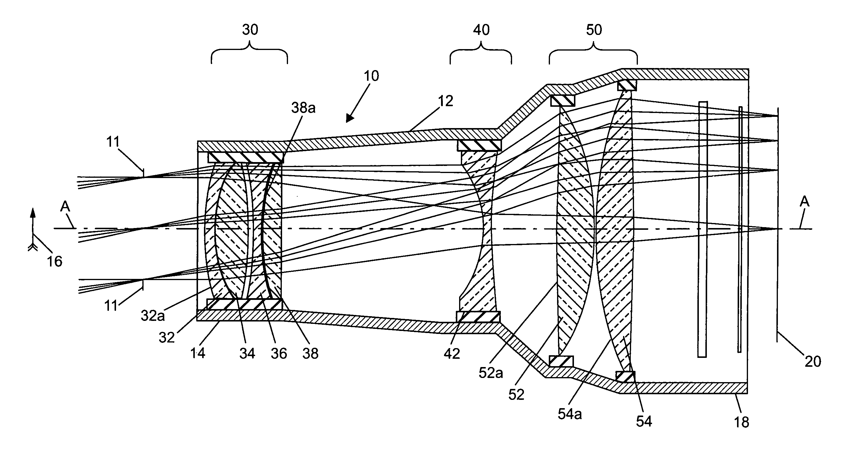
[0043]FIG. 1 shows an apochromatic lens system 10 according to the invention. The system 10 is configured for use with an external aperture stop 11.

[0044]The lens system 10 basically includes a lens barrel 12 having an axis A-A. The barrel 12 is supported by a bracket or other structure not shown in FIG. 1, so as to face a distant object 16 a true and clear image of which is needed for purposes of imaging or projection. The image of the object 16 is formed onto an imaging surface 20 that is aligned with a back end 18 of the barrel. The surface 20 may incorporate, for example, a number of charge coupled devices (CCDs) mounted in a focal plane array (FPA) for converting the image into corresponding electrical (e.g., digital) signals. See the mentioned U.S. Pat. No. 5,333,076 all relevant portions of which are incorporated by reference. In other applications, the imaging surface 20 may constitute a direct viewing surface or screen.

[0045]A first optical group 30, a second optical group ...

second embodiment

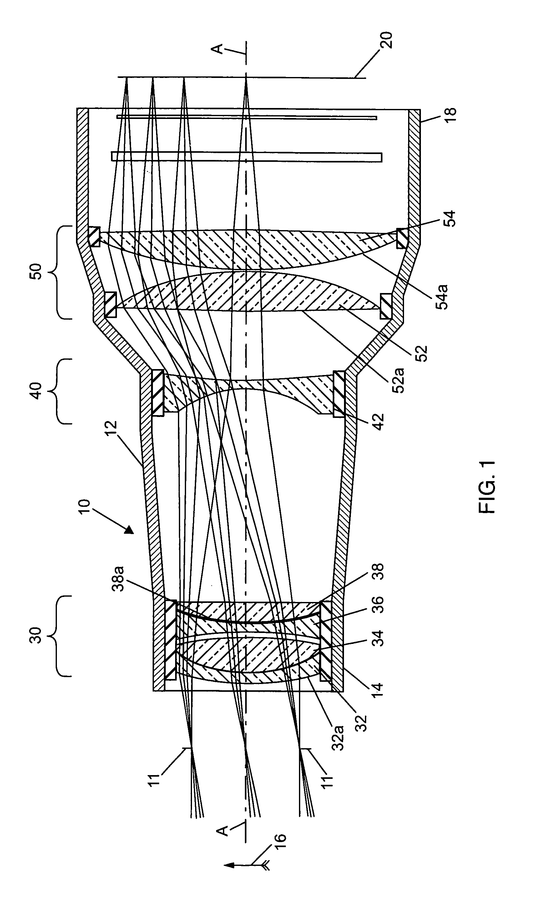
[0063]FIG. 6 shows an apochromatic lens system 110 according to the invention. The system 110 is configured for use with an internal aperture stop 111.

[0064]The system 110 includes a lens barrel 112 having an axis A′-A′. The barrel 112 is supported by a bracket or other structure not shown in FIG. 4 so as to face a distant object 116 a true and sharp image of which is needed for purposes of imaging or projection. The image of the object 116 is projected onto an imaging surface 120 that is aligned with a back end 118 of the barrel. The surface 120 may, for example, incorporate a number of CCDs mounted in a focal plane array for converting the object image into corresponding electrical signals, or constitute a direct viewing surface or screen.

[0065]A first optical group 130, a second optical group 140, and a third optical group 150 of optical elements are mounted inside the lens barrel 112 in the stated order from the front end 114 toward the rear end 118 of the barrel, in alignment w...

third embodiment

[0081]FIG. 11 shows an apochromatic lens system 210 according to the invention. The system 210 is configured for use with an internal aperture stop 211. Parts of the system 210 that correspond to those of the system 110, have the same reference numerals increased by 100.

[0082]The lens system 210 also requires only six optical elements that may be formed from only three different types of glass. For example:

[0083]

Glass MaterialSourceOptical ElementsNLAF2SCOTT236SLAL54OHARA232, 242EADF50HOYA234, 238, 252

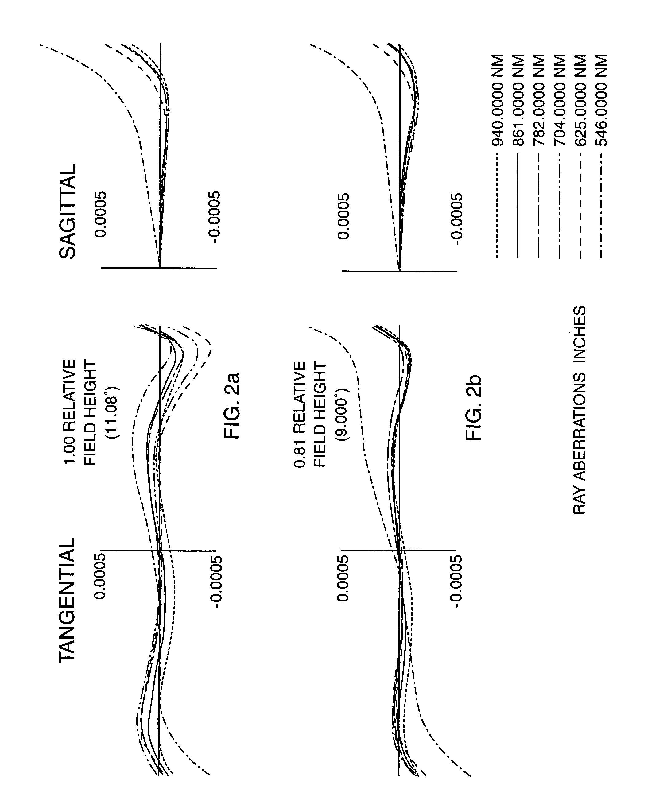
[0084]Further, the following relationships among the optical groups 230, 240, 250 and their constituent optical elements have been found to allow the lens system 210 to perform well over a wide band as shown in FIGS. 12 and 13.

F′I / F′II>2.5;

1<V1 / V2≈V5 / V6<1.2;

0.7V1 / V2) / (V3 / V4)<0.9;

0.25P1 / ΔP2)(ΔP3 / ΔP4)<0.55

where:

[0085]F′I and F′II are the focal lengths of optical groups 230 and 240, respectively;

[0086]V1, V2, V3, V4, V5 and V6 are the Abbe numbers for the optical elements 232, 234, 236...


PUM


Abstract

A wideband, e.g., 550 nm to 940 nm, apochromatic lens system for use with an external aperture stop, includes first, second, and third optical groups having, in order, positive, negative, and positive powers. The first group includes four optical elements having, in order, negative, positive, negative, and positive powers. The second group includes one element of negative power; and the third group includes two elements each having positive power. In another embodiment for use with an internal stop, the system includes first, second, and third optical groups having, in order, positive, positive, and negative powers. The first group includes four optical elements having, in order, positive, negative, positive, and negative powers. The second group includes one element of positive power, and the third group includes one element of negative power. In either embodiment, all of the optical elements are formed from not more than three different types of glass material.

Description

BACKGROUND OF THE INVENTION[0001]1. Field of the Invention[0002]This invention relates to optical lens systems configured to compensate for chromatic aberration, and particularly to an apochromatic lens suitable for wideband applications.[0003]2. Discussion of the Known Art[0004]U.S. Pat. No. 5,333,076 (Jul. 26, 1994) discloses a stabilized imaging system intended for use in aerial reconnaissance systems, including a fixed lens assembly and a movable electro-optic imager element. The lens assembly has an external entrance pupil located between a rotating prism and a stationary prism, so that the apertures of the two prisms can be made relatively small for a given field of view. In addition, the prisms provide a level of compensation for chromatic aberration that occurs within the lens assembly.[0005]Lens assemblies or systems such as disclosed in the '076 patent are constructed to compensate for chromatic dispersion inherent in each lens element of the system. The systems are typica...

Claims


Application Information

Patent Timeline
Patent Type & Authority Patents(United States)
IPC IPC(8): G02B9/12
CPCG02B13/00G02B13/146G02B27/0025
Inventor OSKOTSKY, MARKRUSSO, JR., MICHAEL J.
Owner BAE SYST INFORMATION & ELECTRONICS SYST INTERGRATION INC
Why Eureka
Try Eureka