
Capacitor-input positive and negative power supply circuit

a power supply circuit and capacitor-input technology, applied in the direction of electric variable regulation, process and machine control, instruments, etc., can solve the problems of pumping operation, increased cost, and degradation of operating efficiency

Inactive Publication Date: 2007-04-24
YAMAHA CORP
View PDF22 Cites 56 Cited by
  • Summary
  • Abstract
  • Description
  • Claims
  • Application Information

AI Technical Summary

Benefits of technology

[0016]It is an object of the present invention to provide a power supply circuit which is capable of eliminating an adverse effect of pumping operation, using a simple means.
[0018]According to this power supply circuit, it is possible to prevent a smoothing capacitor from being charged by pumping operation when the capacitor-input positive and negative power supply circuit drives an inductance load, whereby breakage of the capacitor can be prevented. This makes it possible to eliminate the need to use a capacitor having a high breakdown voltage, thereby enabling cost saving and reducing the size of the power supply circuit.

Problems solved by technology

However, when the inductance load is driven by the positive and negative power supply circuit as described above, there is a problem of pumping operation.
As described above, the pumping operation causes imbalance in voltage between the positive power supply and the negative power supply, which results in degradation of operating efficiency.
In this case, however, an increased number of switching transistors capable of driving a low impedance load are needed, which brings about the problem of increased cost.
Further, the circuit configuration for implementing the technique is very complicated.

Method used


Image

  • Capacitor-input positive and negative power supply circuit
  • Capacitor-input positive and negative power supply circuit
  • Capacitor-input positive and negative power supply circuit

Examples


first embodiment

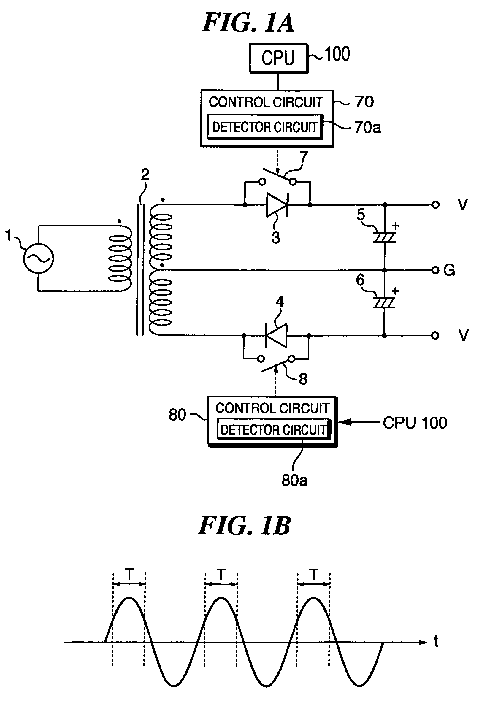
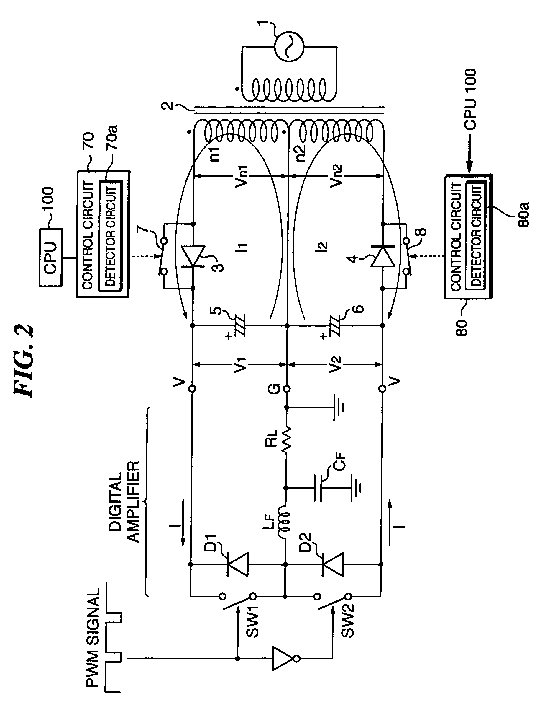
[0033]the present invention will be described with reference to FIGS. 1A, 1B and 2.

[0034]FIG. 1A is a circuit diagram showing the circuit configuration of a power supply circuit according to the first embodiment.

[0035]In FIG. 1A, reference numeral 1 designates an AC power supply, reference numeral 2 designates a transformer having a secondary winding with a center tap, and reference numerals 3 and 4 designate rectifier devices (diodes). Further, reference numeral 5 designates a capacitor connected between the diode 3 and the center tap, and reference numeral 6 designates a capacitor connected between the center tap and the diode 4.

[0036]These component parts 1 to 6 form a capacitor-input positive and negative power supply circuit. In the present embodiment, as shown in FIG. 1A, a switching circuit 7 (hereinafter referred to as “the switching element 7”) is connected in parallel with the diode 3, and a switching circuit 8 (hereinafter referred to as “the switching element 8”) is conn...

second embodiment

[0044]Next, a description will be given of the present invention with reference to FIGS. 3A to 5.

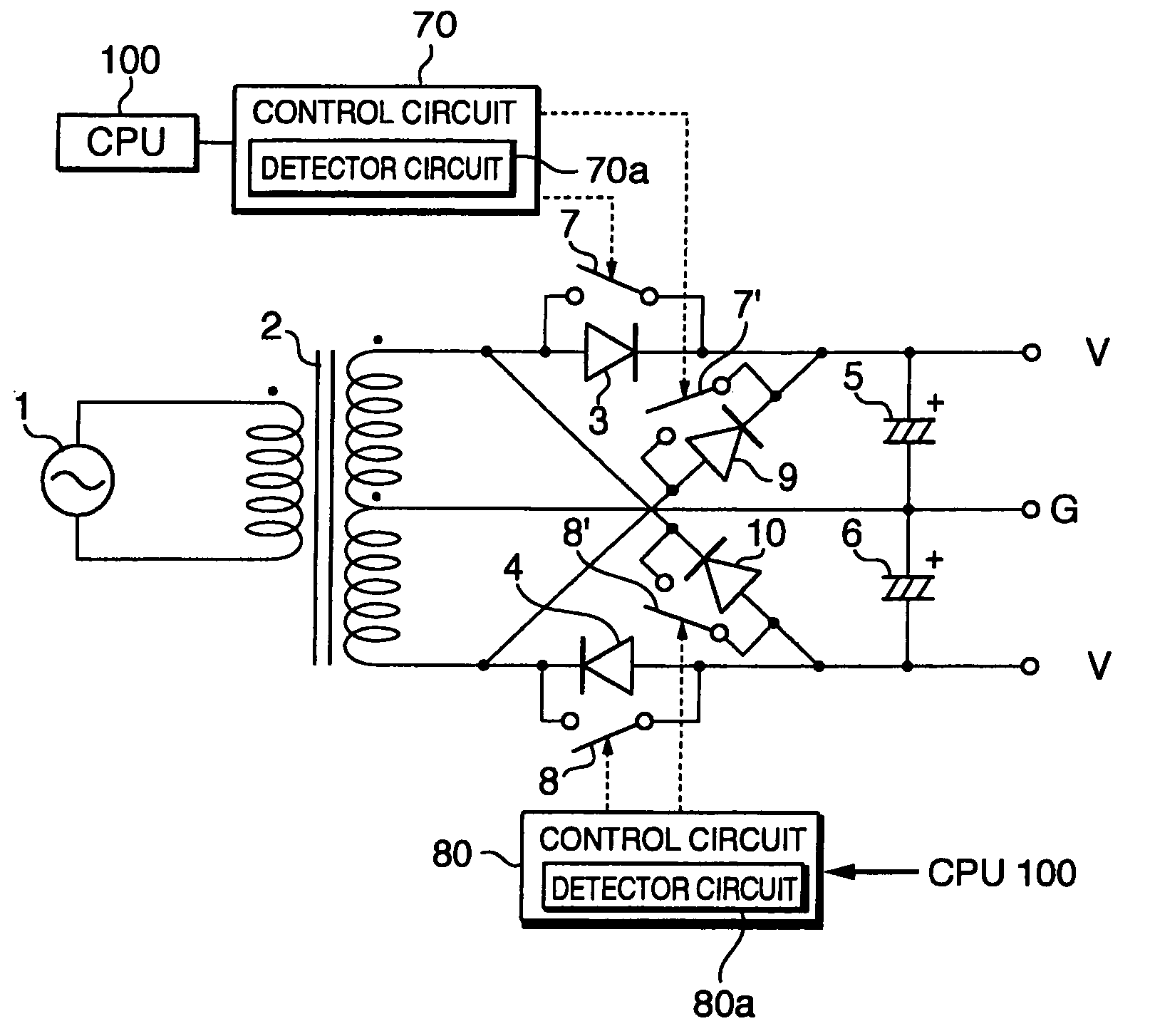
[0045]While the first embodiment is applied to the positive and negative power supply circuit that performs half-wave rectification, shown in FIG. 1A, the second embodiment is applied to a positive and negative power supply circuit that performs full-wave rectification, shown in FIG. 3A.

[0046]The power supply circuit shown in FIG. 3A is distinguished from the power supply circuit shown in FIG. 1A only in that rectifier diodes 9 and 10 are additionally provided to form a bridge rectifier circuit together with the diodes 3 and 4. Out of the four diodes 3, 4, 9 and 10, only the switching element 7 and the switching element 8 are connected in parallel with the respective diodes 3 and 4, even when the power supply circuit employs the bridge rectifier circuit using the four diodes. Even with this connection, the same advantageous effects as described above can be obtained. The switching elemen...


PUM


Abstract

There is provided a power supply circuit having a simple configuration which is capable of eliminating an adverse effect due to pumping operation. The capacitor-input positive and negative power supply circuit is comprised of diodes, switching circuits connected in parallel with the diodes, and control circuits that control the switching circuits such that the switching circuits conduct during a time period over which the diodes conduct.

Description

BACKGROUND OF THE INVENTION[0001]1. Field of the Invention[0002]The present invention relates to a power supply circuit, and more particularly to a power supply circuit that drives an inductance load.[0003]2. Description of the Related Art[0004]FIG. 6 is a circuit diagram showing an example of the circuit configuration of a conventional power supply circuit and a digital amplifier connected thereto.[0005]In FIG. 6, reference numeral 51 designates a transformer, reference numerals 52 and 53 designate rectifier devices (diodes), and reference numerals 54 and 55 designate smoothing capacitors. These component parts form a capacitor-input positive and negative power supply circuit. The transformer 51 has a winding of which one end is connected to the anode of the diode 52 and the other end is connected to the cathode of the diode 53. The cathode of the diode 52 is connected to one end of the smoothing capacitor 54 and a positive voltage (+V) input terminal of the digital amplifier. The ...

Claims


Application Information

Patent Timeline
IPC IPC(8): H02M7/12H02M1/00H02M3/335H02M7/217
CPCH02M3/33576H02M7/217H02M2001/009H02M1/009
Inventor NORO, MASAO
Owner YAMAHA CORP
Learn More