Imaging lens and imaging apparatus using imaging lens

a technology of imaging lens and imaging apparatus, applied in the field of imaging lens, can solve the problems of increasing costs, increasing manufacturing costs, and significant temperature-related performance changes, and achieve the effect of improving environmental resistance without deteriorating lens performance and increasing manufacturing costs

Active Publication Date: 2010-06-10
JIANGXI OFILM OPTICAL CO LTD
View PDF8 Cites 56 Cited by
  • Summary
  • Abstract
  • Description
  • Claims
  • Application Information

AI Technical Summary

Benefits of technology

[0013]In consideration of the above-described situation, an object of the invention is to provide an imaging lens capable of improving environmental resistance without deteriorating lens performance or without causing an increase in manufacturing costs, and an imaging apparatus using the imaging lens.

Problems solved by technology

The imaging lens described in U.S. Pat. No. 7,023,628 is a fast lens having an F number of 2.0, but multiple lenses made of a material having a refractive index larger than 1.9 are used, which causes an increase in costs.
When this imaging lens is used as a lens for an onboard camera or a lens for a surveillance camera, if a lens is made of plastic, a significant change in performance occurs due to temperature.
Further, the use of a lens formed by a glass mold causes an increase in costs.
For this reason, when a lens is made of plastic, a significant change in performance occurs due to temperature.
Further, the use of a lens formed by a glass mold causes an increase in costs.
In an imaging lens using a cemented lens, however, an adhesive material forming an adhesive layer is placed under a severe environment for a long time and then degenerated or modified, so the optical performance of the imaging lens is deteriorated.
Special processing may be performed so as to allow the cemented lens to be used under a severe environment, but this processing causes an increase in costs.
This problem generally occurs when an imaging lens using a cemented lens is used under a severe environment, regardless of whether it is an onboard camera or a surveillance camera.

Method used


Image

  • Imaging lens and imaging apparatus using imaging lens
  • Imaging lens and imaging apparatus using imaging lens
  • Imaging lens and imaging apparatus using imaging lens

Examples


specific examples

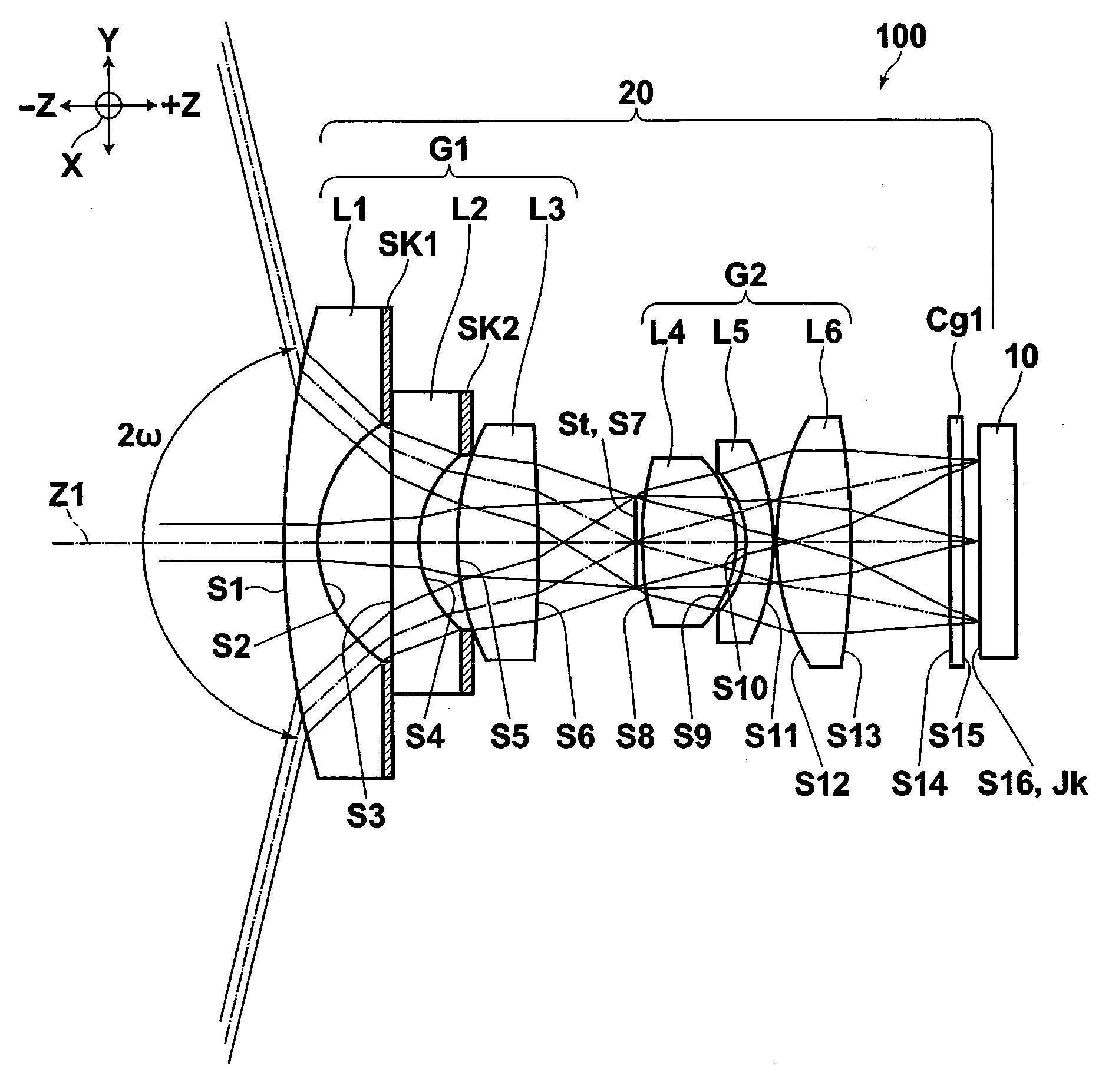
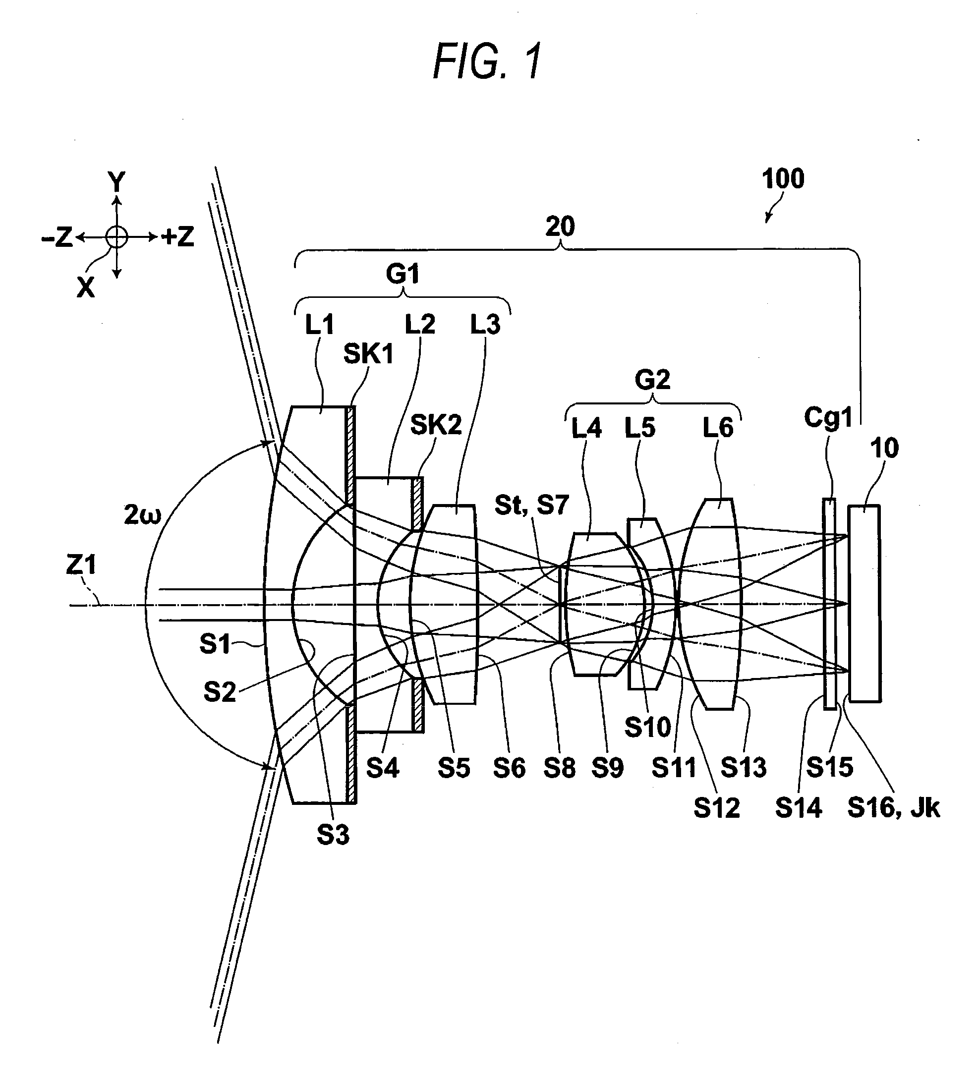
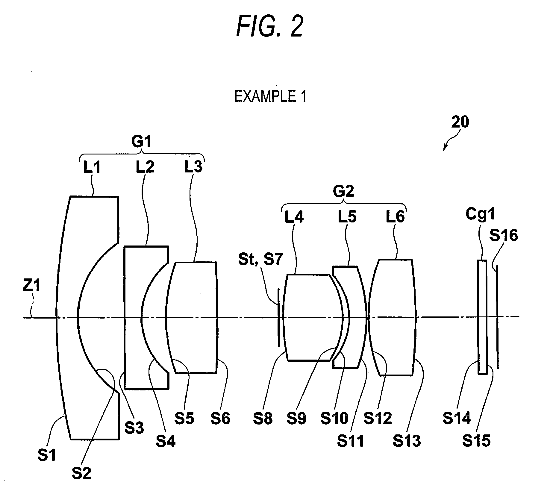
[0199]Next, numerical data and the like in imaging lenses according to Examples 1 to 10 will be described together with reference to FIGS. 2 to 21 and Tables 1 to 11. FIGS. 2 to 11 show the schematic configuration of the imaging lenses according to Examples 1 to 10. In FIGS. 2 to 11, the same reference numerals as the reference numerals in FIG. 1 reference the same elements.

[0200]Tables 1 to 11 described below show basic data of the respective imaging lenses of Examples 1 to 10.

[0201]In Tables 1 to 10, lens data is described in the left portion (in the drawings, indicated by (a)), and the schematic specification of the imaging lens is described in the right portion (in the drawings, indicated by (b)).

[0202]With respect to lens data in the left portions of Table 1 to 10, the surface members of the optical members such as the lenses and the like are indicated by i (where i=1, 2, 3, . . . ) in an ascending order from the object side toward the image side. Lens data also includes the su...


PUM


Abstract

An imaging lens is provided and includes, in order from the object side, a front group having a negative power, a stop, and a rear group having a positive power. The front group includes, in order from the object side, a first negative lens having a meniscus shape with a concave surface on an image side, a second negative lens, and a third positive lens. The rear group includes, in order from the object side, a fourth positive lens, a fifth negative lens having a meniscus shape with a concave surface on the object side, and a sixth positive lens. An Abbe number of each of the first lens, the second lens, the fourth lens, and the sixth lens at the d-line is equal to or larger than 40, and an Abbe number of each of the third lens and the fifth lens at the d-line is equal to or smaller than 40. Each lens constituting the front group and the rear group is a single lens.

Description

[0001]This application is based on and claims priority under 35 U.S.C §119 from Japanese Patent Application Nos. 2008-313893 and 2009-273449, filed on Dec. 10, 2008 and Dec. 1, 2009, respectively, the entire disclosure of which is herein incorporated by reference.BACKGROUND OF THE INVENTION[0002]1. Field of the Invention[0003]The present invention relates to an imaging lens imaging a subject and an imaging apparatus using the imaging lens.[0004]2. Description of Related Art[0005]A compact imaging lens is known which is used in an imaging apparatus, such as an onboard camera or a surveillance camera. An imaging device which includes a compact CCD or CMOS having a large number of pixels for use in such an imaging apparatus, or a compact imaging lens which is assembled with the imaging device is also known.[0006]As an imaging lens used in such an imaging apparatus, imaging lenses described in U.S. Pat. No. 7,023,628, Japanese Patent No. 2599312, JP-A-61-123810, JP-A-2007-279632, and JP...

Claims


Application Information

Patent Timeline
Patent Type & Authority Applications(United States)
IPC IPC(8): G02B9/10
CPCG02B13/04
Inventor ASAMI, TAROOTOMO, RYOKO
Owner JIANGXI OFILM OPTICAL CO LTD
Why Eureka
Try Eureka