Imaging lens and imaging device including the imaging lens

a technology of imaging lens and imaging device, which is applied in the direction of optics, instruments, optical elements, etc., can solve the problems of increased astigmatism, difficult to gain power, and unsuitable lens system for size and weight reduction, and achieve excellent optical performance, reduce size and weight, and high resolution

Inactive Publication Date: 2008-07-31
ENPLAS CORP
View PDF5 Cites 49 Cited by
  • Summary
  • Abstract
  • Description
  • Claims
  • Application Information

AI Technical Summary

Benefits of technology

[0026]In the imaging lens of the invention, an excellent optical performance can be maintained, while sufficiently reducing the size and weight. In particular, various aberrations can be controlled and telecentricity can be maintained, while having high resolution. In addition, the required back focus distance can be secured.

Problems solved by technology

Therefore, power is difficult to gain, and the lens system is not suitable for size and weight reduction.
As a result, a problem in optical performance occurs in that astigmatism increases.
As a result, the lens system is not suitable for size and weight reduction.

Method used


Image

  • Imaging lens and imaging device including the imaging lens
  • Imaging lens and imaging device including the imaging lens
  • Imaging lens and imaging device including the imaging lens

Examples


examples

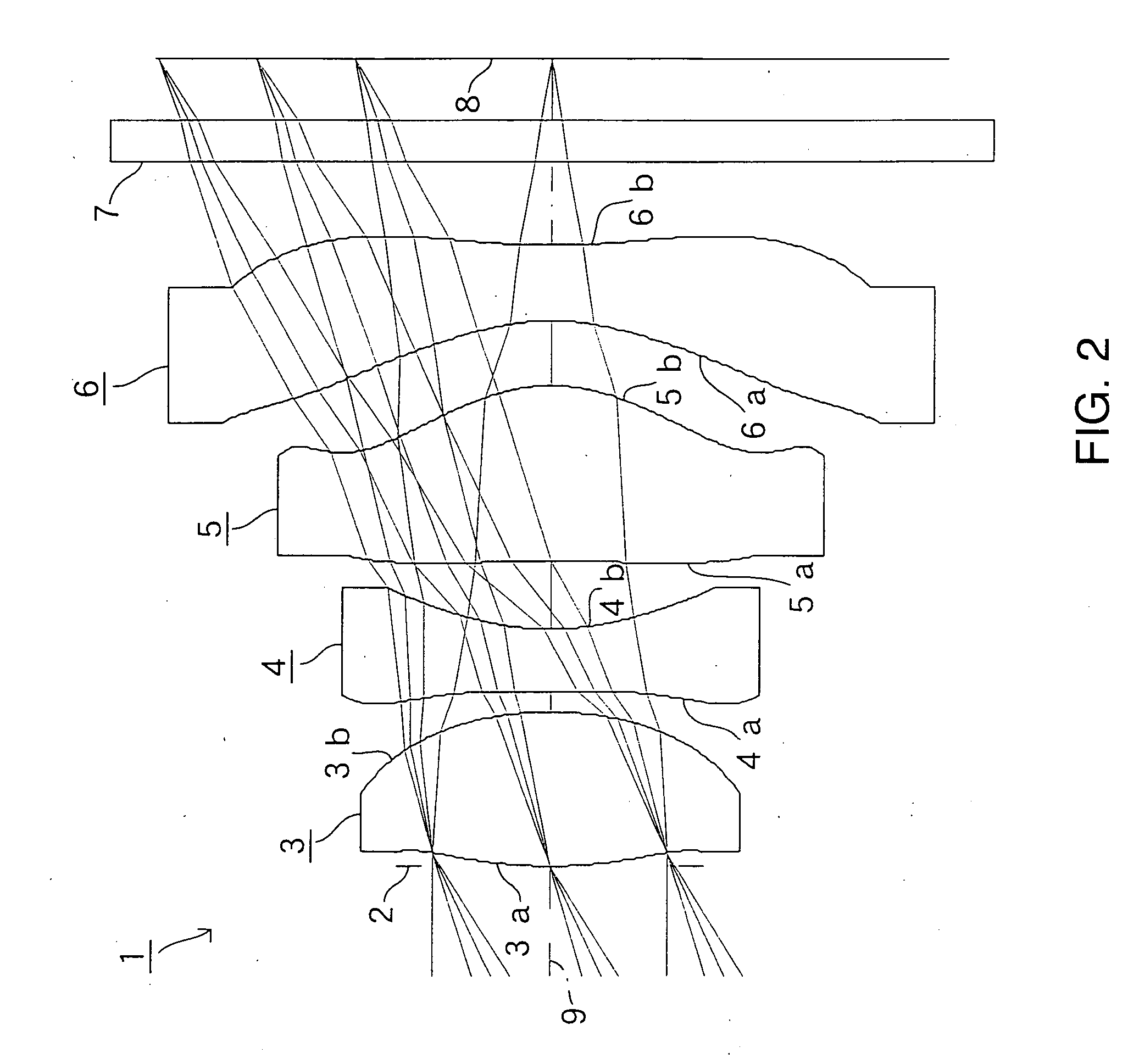
[0099]Next, EXAMPLES of the present invention will be described with reference to FIG. 2 to FIG. 35.

[0100]In the EXAMPLES, Fno denotes F number, ω denotes half of the angle-of-view, and r denotes the radius curvature of an optical surface (center radius curvature of an aspherical surface). Further, d denotes a distance on an optical axis 9 to the next optical surface, nd denotes the index of refraction of each optical system when the d line (yellow) is irradiated, and νd denotes the Abbe number of each optical system also when the d line is irradiated.

[0101]k, A, B, C, D, and E denote each coefficient in a following expression (5). Specifically, the shape of the aspherical surface of the lens is expressed by the following expression provided that the direction of the optical axis 9 is taken as the Z axis, the direction orthogonal to the optical axis 8 (height direction) as the X axis, the traveling direction of light is positive, k is the constant of cone, A, B, C, D, and E are the ...

first example

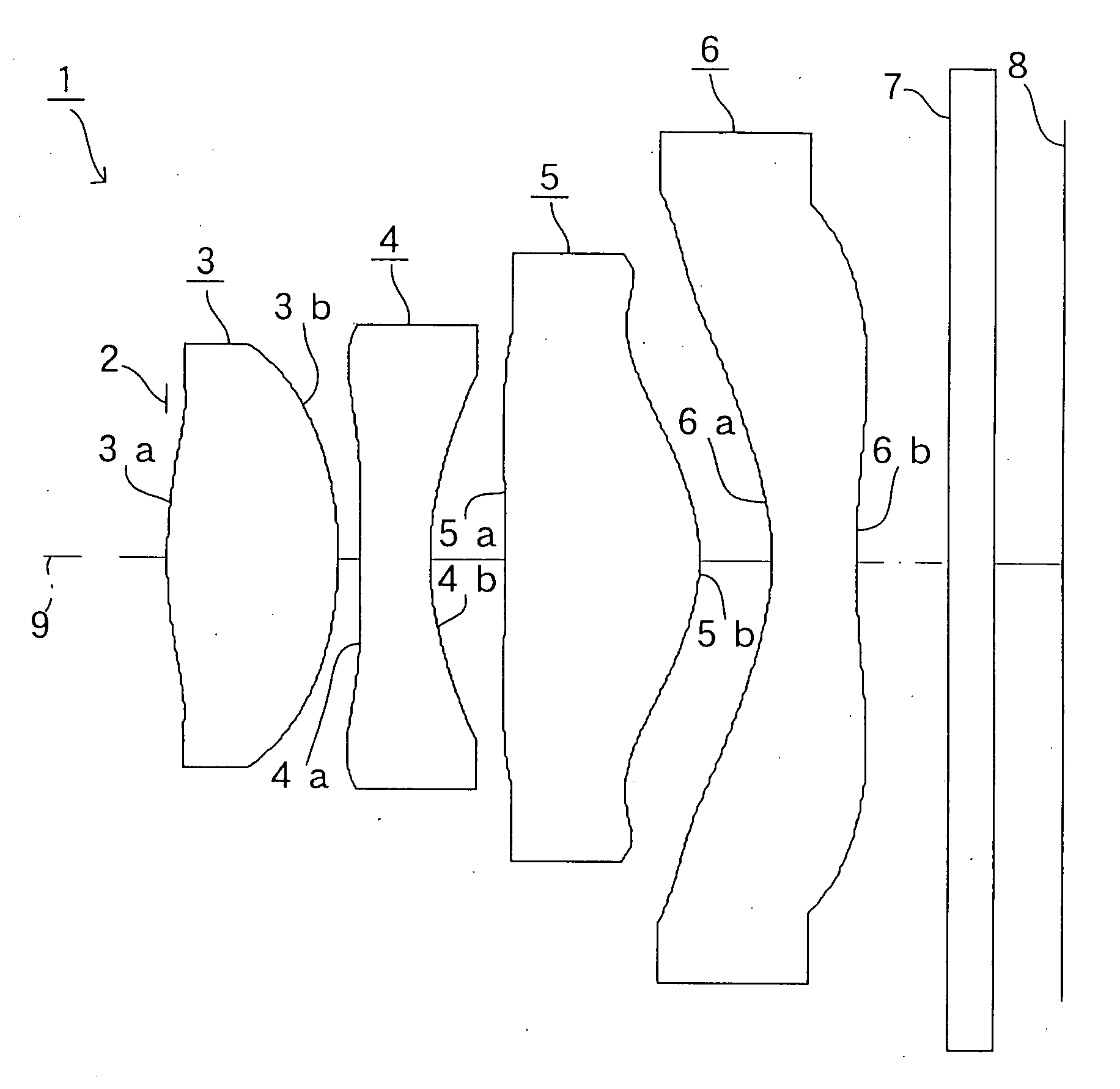
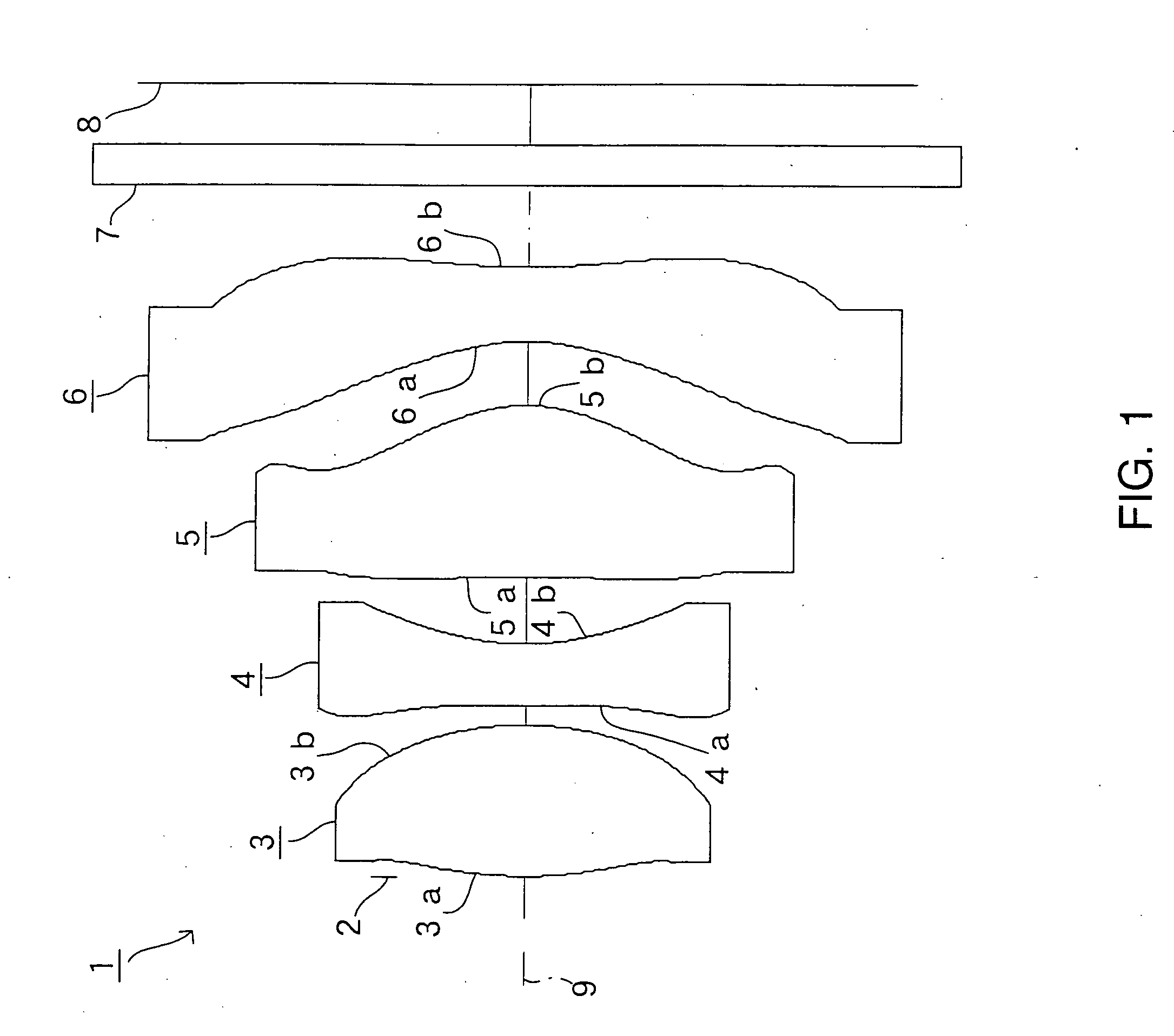
[0103]FIG. 2 shows a FIRST EXAMPLE of the present invention. In the example, a cover glass serving as the filter 7 is disposed between the second face 6b of the fourth lens 6 and the image-taking surface 8. The diaphragm 2 is positioned in the optical axis 9 (Z axis) direction. The position corresponds with a surface peak of the first face 3a of the first lens 3. the shown in FIG. 2 is the same imaging lens 1 as that shown in FIG. 1. Therefore, the diaphragm 2 and the first face 3a of the first lens 3 are given the same face number in the lens data, herebelow.

[0104]The imaging lens 1 of the FIRST EXAMPLE was set under the following conditions:

Lens DataFL = 4.65 mm, Fno = 2.8, ω = 31°Face Numberrdndνd(Object Point)81(First Face of First Lens)2.9891.131.531056.0(Diaphragm)2(Second Face of First Lens)−2.4490.153(First Face of Second Lens)21.2950.451.585030.04(Second Face of Second Lens)1.7630.505(First Face of Third Lens)−10.5531.271.531056.06(Second Face of Third Lens)−1.1620.487(Firs...

second example

[0108]FIG. 4 shows a SECOND EXAMPLE of the present invention. In the example, as in the FIRST EXAMPLE, a cover glass serving as the filter 7 is disposed between the second face 6b of the fourth lens 6 and the image-taking surface 8. A position of the diaphragm 2 in the optical axis 9 direction corresponds with a surface peak of the first face 3a of the first lens 3.

[0109]The imaging lens 1 of the SECOND EXAMPLE was set under the following conditions:

Lens DataFL = 4.65 mm, Fno = 2.8, ω = 31°Face Numberrdndνd(Object Point)81(First Face of First Lens)3.0171.161.531056.0(Diaphragm)2(Second Face of First Lens)−1.6180.103(First Face of Second Lens)−8.3410.481.585030.04(Second Face of Second Lens)1.8370.665(First Face of Third Lens)−3.8920.881.531056.06(Second Face of Third Lens)−1.1370.477(First Face of Fourth Lens)−1.9780.551.531056.08(Second Face of Fourth Lens)4.3460.6010(First Face of Cover Glass)80.301.516864.211(Second Face of Cover Glass)8(Image Surface)FaceNumberkABCDE1−3.21E+18.5...


PUM


Abstract

It is to provide an imaging lens and an imaging device including the imaging lens in which the imaging lens can maintain excellent optical performance, while achieving sufficient reduction in size and weight.The imaging lens comprises, in order from an object side to an image surface side, a diaphragm, a first lens that is a biconvex lens having a positive power, a second lens having a negative power, a third lens having a positive power, and a fourth lens that is a biconcave lens, wherein a condition expressed by 0.7≦FL / f1≦3.0 (where, FL: focal distance of the entire lens system, and f1: focal distance of the first lens) is to be satisfied.

Description

BACKGROUND OF THE INVENTION[0001]1. Field of the Invention[0002]The present invention relates to an imaging lens and an imaging device including the imaging lens. In particular, the present invention relates to an imaging lens and an imaging device including the imaging lens, in which the imaging lens has a four-lens structure that is suitable for forming an image of an object on an image-taking surface of an image sensor element, such as a charge-coupled device (CCD) and a complementary metal oxide semiconductor (CMOS), mounted on a portable computer, a television phone, a portable phone, a digital camera, a monitoring camera for a vehicle, and the like.[0003]2. Description of the Related Art[0004]In recent years, there has been an increasing demand for cameras that utilize an image sensor element (solid image sensor element), such as the CCD and the CMOS, that is mounted on a portable computer, a television phone, a portable phone, a digital camera, a monitoring camera for a vehic...

Claims


Application Information

Patent Timeline
Patent Type & Authority Applications(United States)
IPC IPC(8): G02B9/34
CPCG02B13/004G02B9/34
Inventor NAKAMURA, AKIRA
Owner ENPLAS CORP
Why Eureka
Try Eureka