Transmission device of layshaft type

a transmission device and layshaft technology, applied in the direction of belt/chain/gearing, toothed gearing, belt/chain/gearing, etc., can solve the problems of short service life of the transmission, increase production costs and the required installation space of the transmission, and undesirable with regard to the operation cost, so as to achieve the effect of improving the structure of the transmission housing

Active Publication Date: 2007-09-25
ZF FRIEDRICHSHAFEN AG
View PDF5 Cites 30 Cited by
  • Summary
  • Abstract
  • Description
  • Claims
  • Application Information

AI Technical Summary

Benefits of technology

[0008]The inventive transmission device of a countershaft type having one input central shaft and concentrically disposed thereto one input hollow shaft and having two powershift elements in which one first half of the shifting elements is operatively connected with one input unit and one second half of the shifting elements is connected with the input shaft or the input hollow shaft. The input central shaft, the input hollow shaft and countershafts are supported in one housing and operatively connected with gear wheels which, as gear wheel pairs, are engaged with each other in pairs and can be connected and disconnected to produce a transmission total ratio in the power flow, has favorable load characteristic values and a long service life, in turn, resulting therefrom.
[0009]This is achieved by the fact that the transmission input central shaft is directly supported in the housing in the area of its end remote from the input unit via a first bearing device and in the area of its second end facing the input unit is supported on the shaft operatively connected with the motor output shaft via a second bearing device; the transmission input hollow shaft being supported directly on the transmission input central shaft via a third bearing device and a fourth bearing device. Thus, in the area of the transmission input shafts, compared to the devices known from the prior art, the inventive solution has less bearings on the housing side and, as result of the inventive bearing device in the area of the transmission input shafts, stands out by low load characteristic values.
[0012]By the proposed solution, other advantages also result in relation to an assembly of the inventive device since, in the first place, the transmission input central shaft can be mounted in the housing of the transmission device. The input hollow shaft can then be easily shoved and secured on the input central shaft.
[0013]The inventive bearing device of the transmission device, in addition, offers advantages regarding the structure of the transmission housing, since the first bearing device and one fixed bearing of a countershaft designed as a central shaft can be positioned in a common bearing plane and can thus be supported in a common bearing plate favorably as to cost and space.

Problems solved by technology

This arrangement, however, is disadvantageously distinguished by unfavorable load characteristic values which result in a short service life of the transmission and undesirable with regard to the operation costs of a motor vehicle throughout the service life thereof.
Furthermore, supports of wheel sets on the housing side, in general, increase the production costs and the required installation space of a transmission, in addition, making and assembly difficult.

Method used


Image

  • Transmission device of layshaft type
  • Transmission device of layshaft type
  • Transmission device of layshaft type

Examples


Embodiment Construction

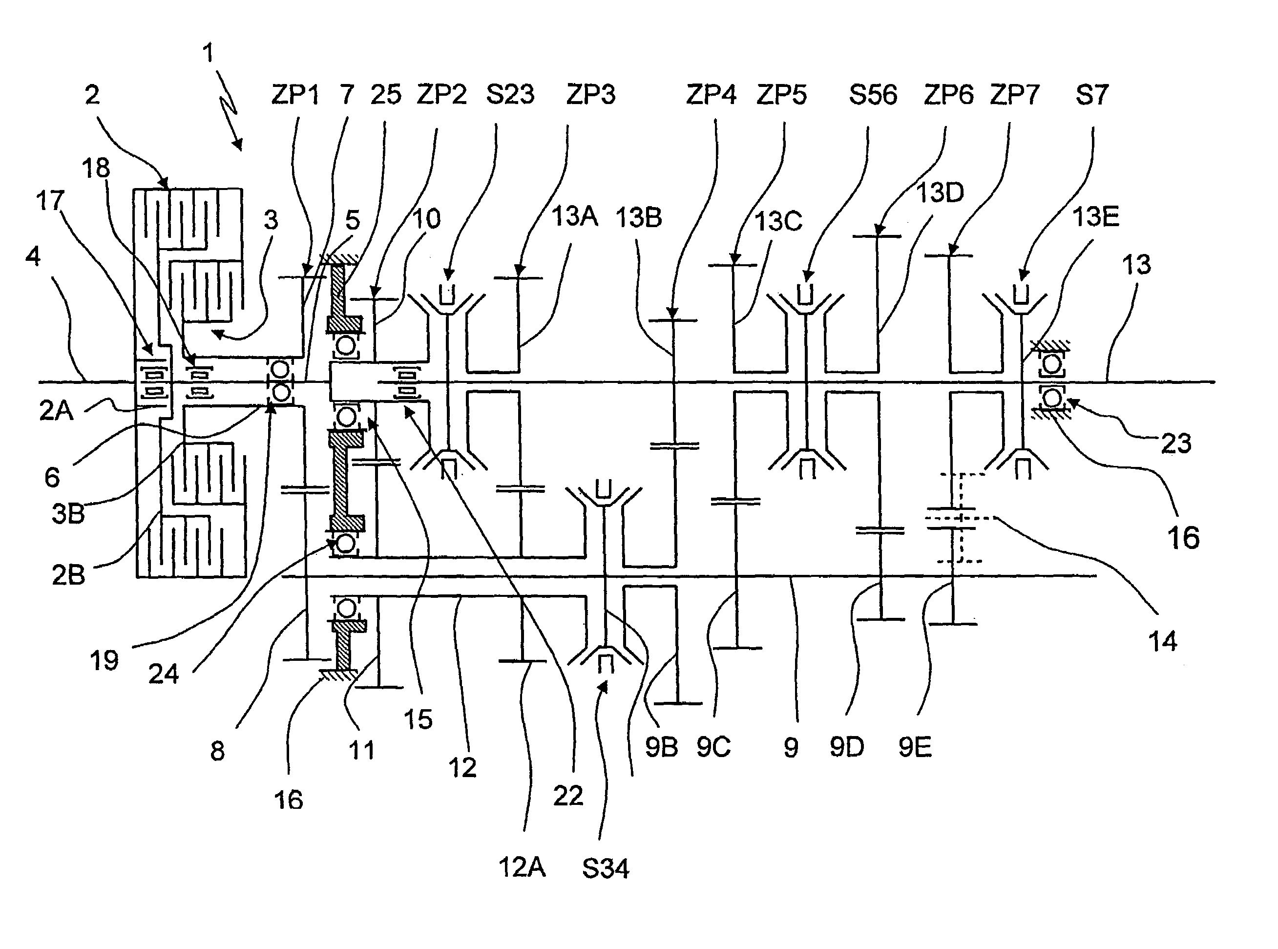
[0018]FIG. 1 shows one transmission device 1 of a countershaft type designed on the input side with two powershift elements 2, 3 by way of which a torque cropping out via a motor output shaft 4 can optionally be passed to an input central shaft 5 or to a second input shaft 6 disposed concentrically to the input central shaft 5, supported thereon and designed as a hollow shaft.

[0019]The second powershift element 3 is situated radially within the first powershift element 2 so that the transmission device 1 designed as a multi-gear transmission or so-called dual clutch transmission has less length in axial direction than in powershift elements disposed side-by-side. The radially nested arrangement of the powershift elements 2, 3 shown in FIG. 1 increase the measurements of the multi-gear transmission 1 on the input in peripheral direction compared to powershift elements disposed side-by-side.

[0020]The input hollow shaft 6 is non-rotatably connected with a first gear wheel 7, designed a...


PUM


Abstract

A countershaft-type transmission device has an input central shaft and an input hollow shaft and two powershift elements. One first half of the powershift elements is in connection with one drive unit and a second half of the powershift elements is connected with the input central shaft or the input hollow shaft. The input central shaft, the input hollow shaft and countershafts are supported in one housing and connected with gear wheels, which are engaged with each other by pairs and can be connected and disconnected to produce a transmission total ratio in the power flow. The input central shaft is supported in the housing via a first bearing device and the drive unit is supported via a second bearing device on a shaft connected with a drive unit, the input hollow shaft being supported on the input central shaft via a third bearing device and a fourth bearing device.

Description

[0001]This application claims priority from German Application Serial No. 10 2004 043 386.0 filed Sep. 8, 2004.FIELD OF THE INVENTION[0002]The invention relates to a transmission device of countershaft type, particularly to a dual clutch transmission, having one input central shaft and concentrical thereto one input hollow shaft.BACKGROUND OF THE INVENTION[0003]DE 43 30 170 C2 disclosed a six-gear dual clutch transmission designed on the input side with a so-called dual clutch formed by two frictionally coupled shifting elements. In this dual clutch transmission, input torque of a prime mover applied via a motor output shaft, depending on a transmitting capacity adjusted at the time in the shifting elements, is passed to a first central input shaft or to a second input shaft supported on the central input shaft and designed as a hollow shaft. The input central shaft and the input hollow shaft are each non-rotatably connected with one gear wheel which, in turn, meshes with respective...

Claims


Application Information

Patent Timeline
Patent Type & Authority Patents(United States)
IPC IPC(8): F16H3/08
CPCF16H3/006Y10T74/19233F16H2003/0933
Inventor GUMPOLTSBERGER, GERHARDPATZNER, JENS
Owner ZF FRIEDRICHSHAFEN AG
Why Eureka
Try Eureka