System and method for setup of toner concentration target for a toner concentration sensor

a technology of toner concentration sensor and setup method, which is applied in the field of electrotrophotographic printing, can solve problems such as difficulty in real-time generation of development curves

Inactive Publication Date: 2007-09-25
XEROX CORP
View PDF10 Cites 1 Cited by
  • Summary
  • Abstract
  • Description
  • Claims
  • Application Information

AI Technical Summary

Problems solved by technology

Therefore, it is difficult to generate a development curve in real-time.

Method used


Image

  • System and method for setup of toner concentration target for a toner concentration sensor
  • System and method for setup of toner concentration target for a toner concentration sensor
  • System and method for setup of toner concentration target for a toner concentration sensor

Examples


Embodiment Construction

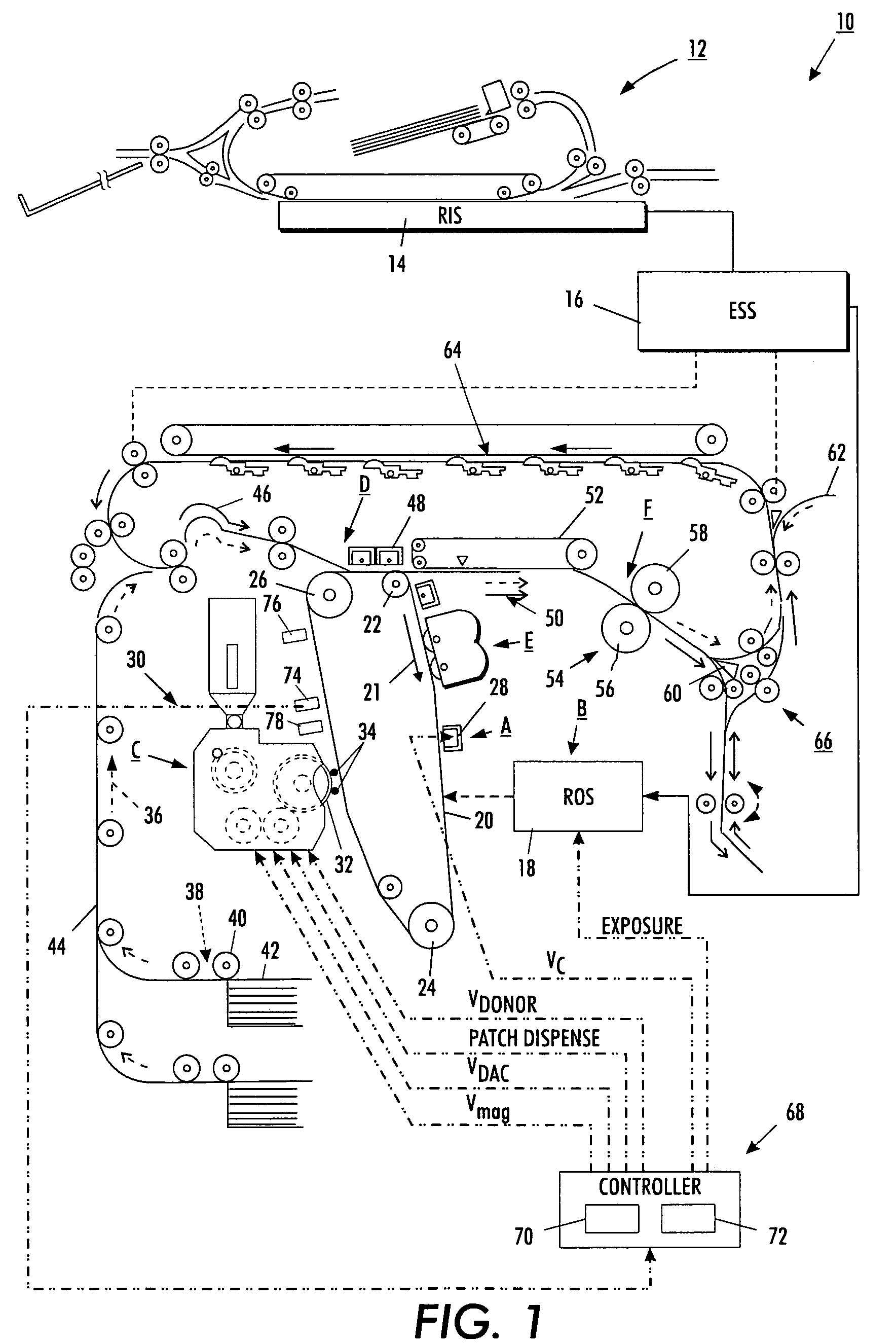
[0013]For a general understanding of the features of the present exemplary embodiment, reference is made to the drawings, wherein like reference numerals have been used throughout to designate identical elements. FIG. 1 schematically depicts the various elements of an illustrative electrophotographic printing machine 10 incorporating the method of the present exemplary embodiment therein. It will become evident from the following discussion that this method is equally well suited for use in a wide variety of printing machines and is not necessarily limited in its application to the particular embodiment depicted herein. Inasmuch as the art of electrophotographic printing is well known, the various processing stations employed in the printing machine 10 will be shown hereinafter and their operation described briefly with reference thereto.

[0014]Referring to FIG. 1, an original document is positioned in a document handler 12 on a raster input scanner (RIS) 14. The RIS 14 contains docu...


PUM


Abstract

A method by which the target of a toner concentration (TC) sensor can be set up based on the equivalent developability concept without using an expensive patch generator. First, use a black toner area coverage (BTAC) sensor to measure the relative reflectance (RR) of a 100% area coverage developed patch (ROS generated) at a series of development levels (Vem or Vdev) to generate a pseudo development curve and estimate VdO in real-time (VdO is the Vdev level that starts to develop toner onto the photoreceptor belt.) Then, add a nominal delta Vdev to VdO to get the development level (Vdev) needed to generate 100% area coverage gray patch. Finally, using a BTAC sensor to measure the RR level of a 100% area coverage (AC) gray patch, move the target of the TC sensor, and converge the sensor's reading to the sensor's target continuously until the RR level of the gray patch hits the RR target (predefined) within the tolerance range. Thus, the target of the TC sensor is set for the xerographic system automatically.

Description

BACKGROUND[0001]The present exemplary embodiment relates generally to electrophotographic printing. It finds particular application in conjunction with setting the target of a toner concentration sensor in an electrophotographic printing machine, and will be described with particular reference thereto. However, it is to be appreciated that the present exemplary embodiment is also amenable to other like applications.[0002]In xerographic print engines, there is normally a toner concentration (TC) sensor located in the sump of the developer housing. Most low cost TC sensors only output only relative TC information, not absolute TC information. Also TC variability from the same sensor target is due to several factors, including sensor manufacturing variability, environmental changes, developer aging characteristics, and characteristics of sensor aging due to mechanical wear. In the past, to determine if the TC level is correct, xerographic systems used expensive calibrated LED bars call...

Claims


Application Information

Patent Timeline
Patent Type & Authority Patents(United States)
IPC IPC(8): G03G15/00G03G15/10
CPCG03G15/5041
Inventor MO, SONG-FENGAPTON, WENDY K.WAGNER, JENNIFER R.RANDALL, STEPHEN F.MEDINA, PATRICIO G.WALKER, PATRICK J.AMAN, RICHARD A.
Owner XEROX CORP
Why Eureka
Try Eureka