
Fuel cell system and current control method thereof

A fuel cell system and fuel cell technology, applied in battery/fuel cell control devices, fuel cells, fuel cell additives, etc., can solve problems such as controllability decline, and achieve the effect of improving controllability

Active Publication Date: 2010-03-24
TOYOTA JIDOSHA KK
View PDF2 Cites 13 Cited by
  • Summary
  • Abstract
  • Description
  • Claims
  • Application Information

AI Technical Summary

Problems solved by technology

[0008] However, when the required current is corrected by PI compensation, if the gain of PI compensation is constant based on the current current point, there is a concern that the controllability will decrease.

Method used


Image

  • Fuel cell system and current control method thereof
  • Fuel cell system and current control method thereof
  • Fuel cell system and current control method thereof

Examples


Embodiment Construction

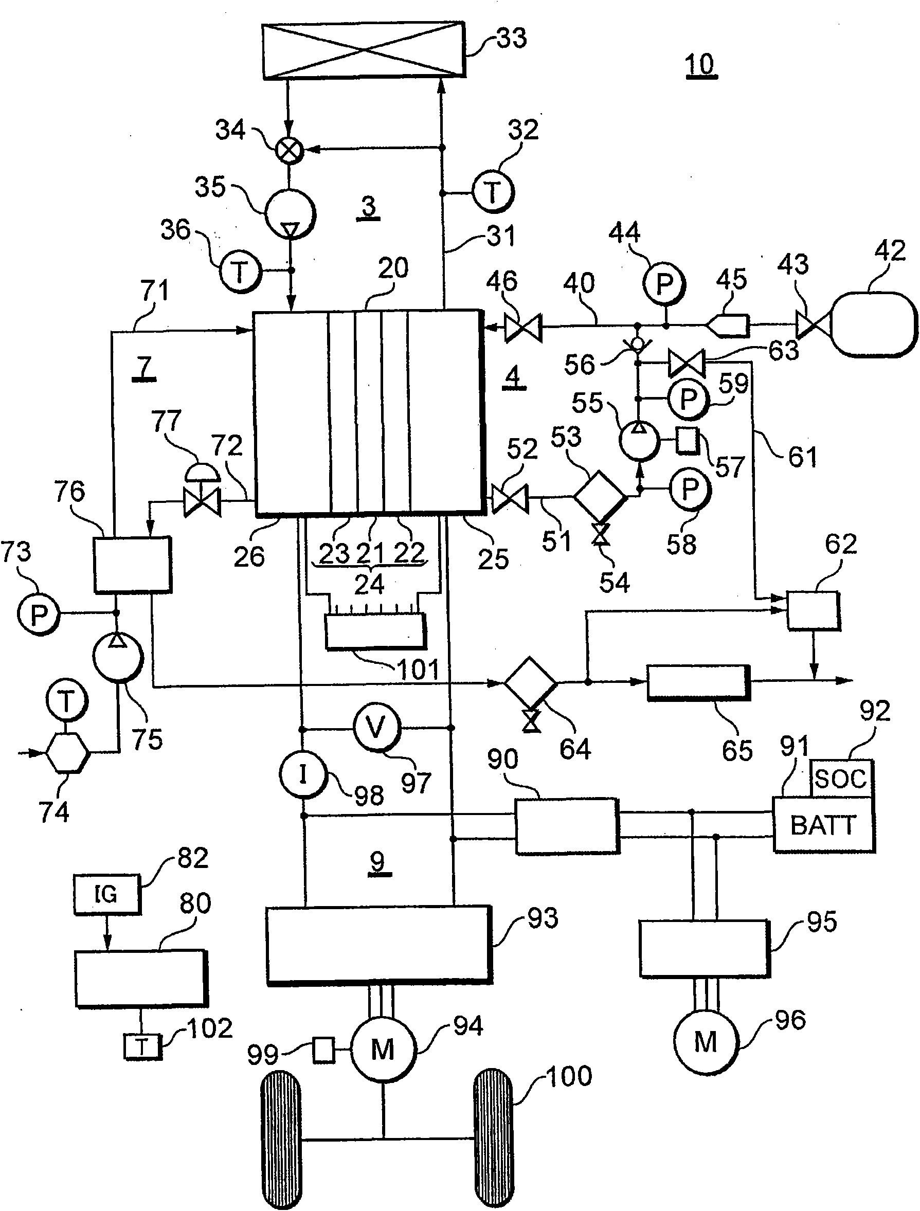
[0033] figure 1 It is a system configuration diagram of a fuel cell system to which the present invention is applied.

[0034] exist figure 1 Among them, the fuel cell system 10 is configured to include: a fuel gas supply system 4 for supplying fuel gas (hydrogen gas) to the fuel cell 20; an oxidizing gas supply system 7 for supplying an oxidizing gas (air) to the fuel cell 20; A coolant supply system 3 for cooling the fuel cell 20 ; and an electric power system 9 for charging and discharging electric power generated from the fuel cell 20 .

[0035] The fuel cell 20 includes a membrane / electrode assembly (MEA) 24 on both surfaces of a polymer electrolyte membrane 21 formed of a proton-conductive ion exchange membrane or the like formed of a fluororesin or the like. The anode 22 and the cathode 23 are formed by screen printing or the like. Both sides of the membrane / electrode assembly 24 are sandwiched by separators (not shown) having flow paths for fuel gas, oxidizing gas, ...


PUM


Abstract

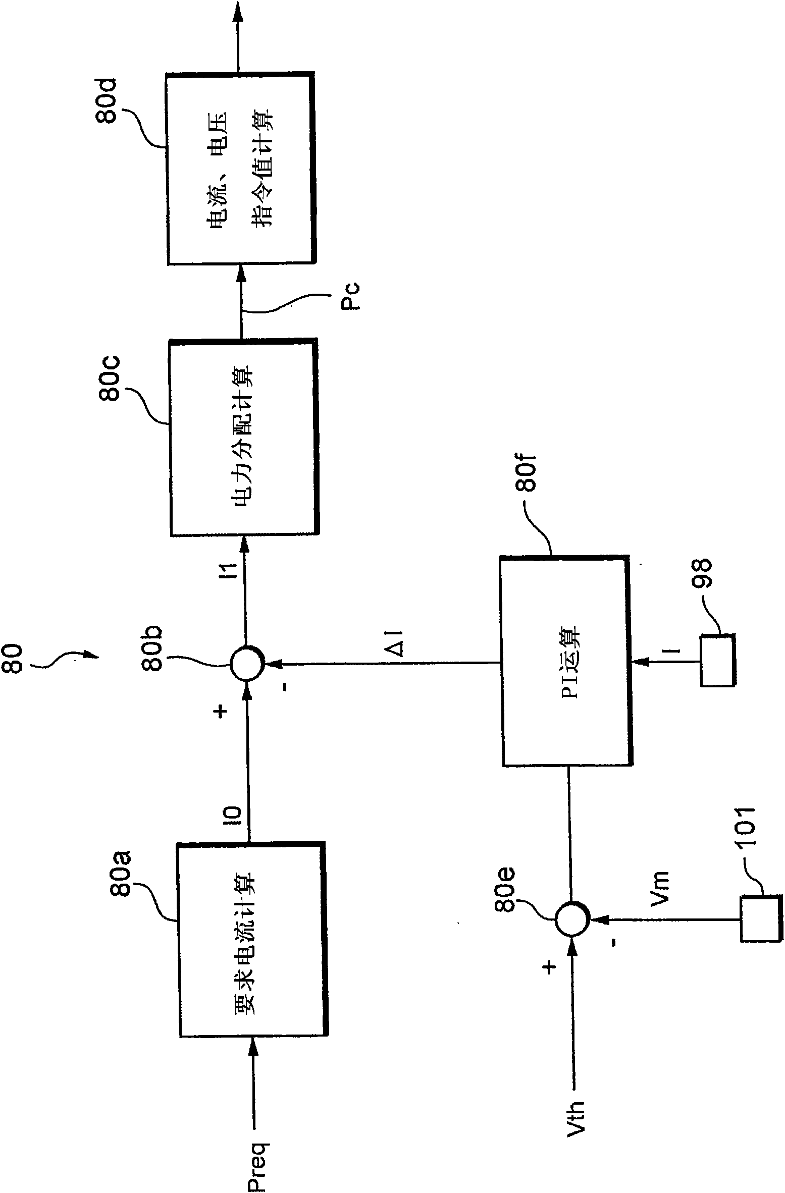
The invention provides a fuel cell system and a current control method thereof. A control unit (80) calculates a request current IO according to a system request power Preq. Upon calculation of a target current I1 by correcting a request current IO by a PI compensation calculation according to a minimum cell voltage Vm by detection of a cell monitor (101), the control unit (80) variably modifies aproportional gain Kp according to a current value at the present point when using a current limit value Delta I as a correction value of the request current IO according to Delta I = Delta V x Kp + Sigma Delta V x Ki, thereby improving control performance for making the current of a fuel cell (20) to be a target current value I1. When correcting the request current by PI compensation using a difference between a minimum cell voltage and a threshold value voltage so as to obtain a target current value and control current of the fuel cell, it is possible to improve the controllability for making the current of the fuel cell to be a target current value.

Description

technical field [0001] The present invention relates to a fuel cell system comprising a fuel cell having a plurality of cells, particularly in relation to current limiting when the system requires power control. Background technique [0002] A fuel cell that generates electricity by utilizing an electrochemical reaction between hydrogen and oxygen includes, for example, a solid polymer fuel cell. This solid polymer fuel cell includes a battery pack constituted by stacking a plurality of single cells. A single cell constituting a battery pack has an anode (fuel electrode) and a cathode (air electrode), and a solid polymer electrolyte membrane having a sulfonic acid group as an ion exchange group is interposed between the anode and the cathode. [0003] A fuel gas containing fuel gas (reformed hydrogen obtained by reforming hydrogen or hydrocarbon to become rich in hydrogen) is supplied to the anode, and an oxidant gas (oxidant gas) such as air is supplied to the cathode. Wh...

Claims


Application Information

Patent Timeline
Patent Type & Authority Applications(China)
IPC IPC(8): H01M8/04B60L11/18H01M8/10
CPCY02T90/34B60L11/1887B60L11/1894H01M8/0491B60L11/1892Y02E60/50B60L11/1881H01M8/04552B60L58/30B60L58/33B60L58/34B60L58/40Y02T10/70Y02T90/40
Inventor 今西启之真锅晃太小川朋也
Owner TOYOTA JIDOSHA KK
Learn More