
Method for detecting and controlling free loops by thin-strip continuous casting

A control method and looper technology, which are applied in the field of free looper detection and control in thin strip continuous casting, can solve the problems of complex strip deformation, high protection requirements for measuring devices, uncertain free looper effect, etc., and achieve good stability. , The adjustment method is direct and reliable, and the effect of avoiding cracks

Active Publication Date: 2011-08-03
BAOSHAN IRON & STEEL CO LTD
View PDF5 Cites 13 Cited by
  • Summary
  • Abstract
  • Description
  • Claims
  • Application Information

AI Technical Summary

Problems solved by technology

However, the protection requirements for measuring devices are relatively high.
[0019] In Japanese Patent JP01130847A, a device and method for directly contacting and detecting the looper on the upper part of the looper is also used, and when the looper changes, the position of the looper is adjusted through the guide roller on the upper part of the looper. This method is very good, but The effect of directly tightening the free looper can not be determined, because the deformation of the strip at this time is more complicated

Method used


Image

  • Method for detecting and controlling free loops by thin-strip continuous casting
  • Method for detecting and controlling free loops by thin-strip continuous casting
  • Method for detecting and controlling free loops by thin-strip continuous casting

Examples


Embodiment Construction

[0050] The present invention will be further described below by embodiment.

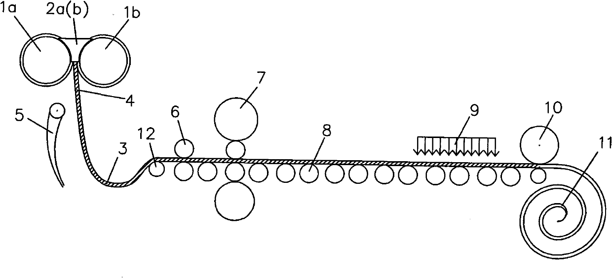
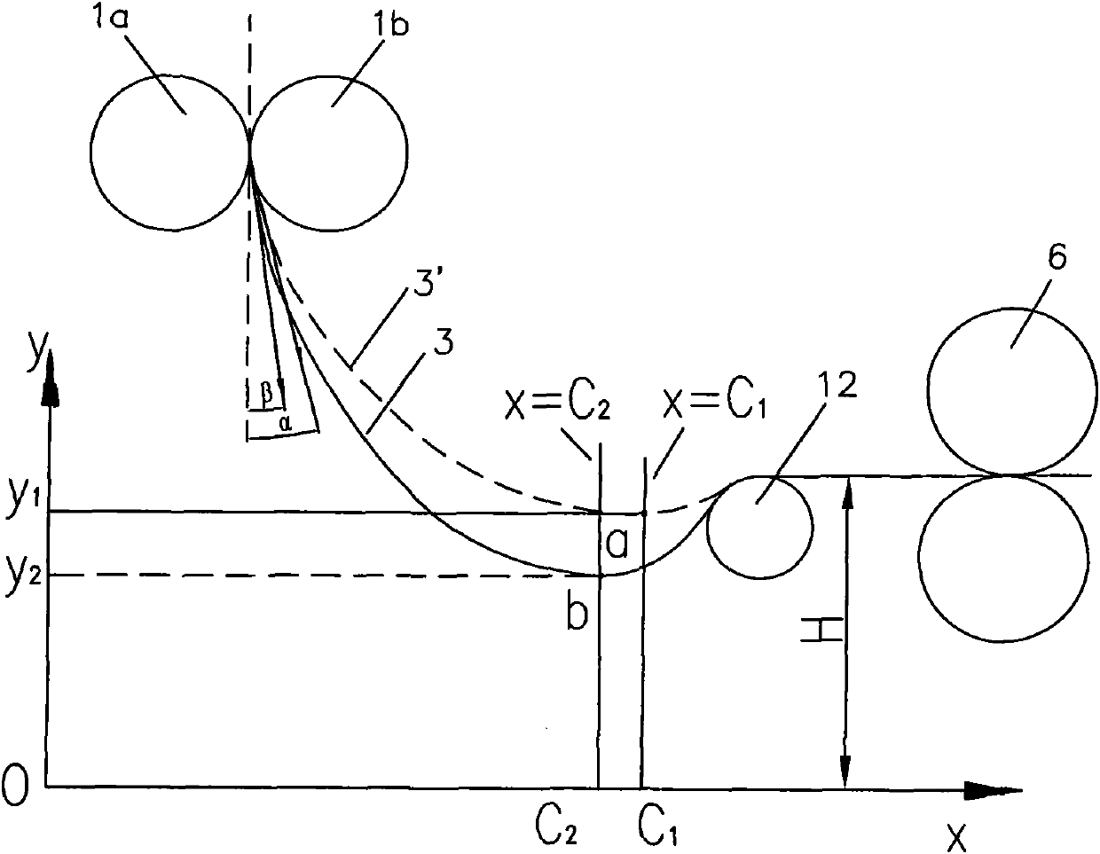
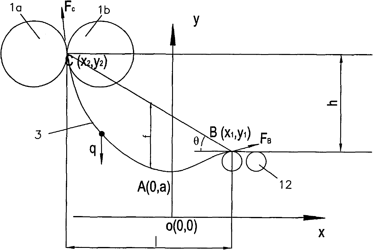
[0051] see Figure 1 to Figure 5 , similar to the typical thin strip continuous casting process, in this example, it includes two relatively rotating cooling rolls 1a, 1b and side sealing plates 2a, 2b capable of rapid cooling, looper guide rolls 12, and a device for adjusting the position of the looper guide rolls Oil cylinders 13, 14 and pinch rollers 6 form loopers 3, 3' between looper guide rollers 12 and cooling rollers 1a, 1b. Since the position of the cooling roll is higher than that of the looper guide roll, the looper formed between the two is of unequal height. Oil cylinders 13, 14 can make the left and right bearing seats of the looper guide rollers move forward and backward synchronously along the advancing direction of the casting band.

[0052] In the loop detection and control system in this embodiment, include: loop detection value processor 15, comparator 16, main controller 17, fr...


PUM


Abstract

The invention relates to a method for detecting and controlling free loops by thin-strip continuous casting, which comprises the following steps that: infrared loop detectors are arranged at front and rear end points of the loops; angles alpha 1 and alpha 2 corresponding to the loop height at a central point of the width of a casting strip are measured by the loop detectors simultaneously to calculate a real value h of the loop height of the casting strip; after the loops are formed and reach a set target h0, the speed of pinch rollers is consistent with that of a cooling roller, a value of the loop quantity is constant basically, and the speed of the pinch rollers is changed correspondingly according to the change of the loop quantity in the process of forming the loops so as to form closed loop control; and the loop height h is changed by the change speed v of the pinch rollers, and the speed change rate delta v is determined according to the actual loop height and real-time speed of strip steel. In the method, an included angle between the forward direction of the strip steel at an outlet (a nip point) of the cooling roller and a vertical casting center line is kept within an ideal range in which cracks cannot be generated on the strip steel when the loops are changed due to the change of a thin-strip continuous casting process so as to prevent the quality defect of the casting strip due to the change of the loops and maintain casting continuity.

Description

technical field [0001] The invention relates to a continuous casting process, in particular to a detection and control method for a thin strip continuous casting free looper. Background technique [0002] Twin-roll thin strip continuous casting technology is an advanced short-flow metallurgical process, see figure 1 , which directly pours molten steel into a molten pool surrounded by two relatively rotating cooling rolls 1a, 1b capable of rapid cooling and side sealing plates 2a, 2b, and the molten steel is cooled and cooled on the circumferential surface of the cooling roll rotation solidify, and then form a solidified shell and gradually grow and then be squeezed together at the smallest gap between the two crystallization rollers 1a and 1b to form a steel strip 4, and the strip 4 is guided to the looper guide roller 12 and the pinch roller 6 through the guide plate 5, And a free loop 3 is formed between the loop guide roll 12 and the cooling roll 1a, 1b, and then rolled ...

Claims


Application Information

Patent Timeline
IPC IPC(8): B22D11/06B22D11/16
Inventor 叶长宏方园顾龙发张健于艳吴建春
Owner BAOSHAN IRON & STEEL CO LTD
Learn More