Hole position correcting method of automatic hole forming system

A correction method and automatic system technology, applied in the direction of automatic control devices, manufacturing tools, metal processing machinery parts, etc., can solve problems such as complex aerodynamic shapes

Active Publication Date: 2019-02-12
TSINGHUA UNIV
View PDF3 Cites 16 Cited by
  • Summary
  • Abstract
  • Description
  • Claims
  • Application Information

AI Technical Summary

Problems solved by technology

[0005] In view of the problems existing in the background technology, the object of the present invention is to provide a hole position correction method for an automatic hole making system, which can not only solve the problem of hole position deviation calculation on workpieces with complex aerodynamic shape and local weak stiffness deformation, It also improves the calculation accuracy of the hole position deviation

Method used


Image

  • Hole position correcting method of automatic hole forming system
  • Hole position correcting method of automatic hole forming system
  • Hole position correcting method of automatic hole forming system

Examples


Embodiment Construction

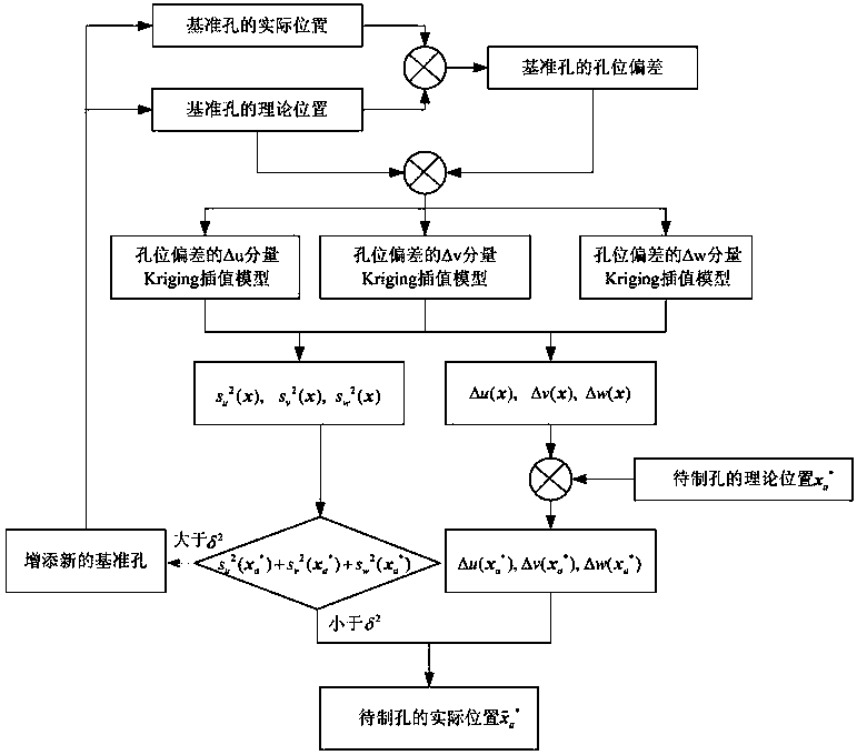
[0052] The hole position correction method of the automatic hole making system according to the present invention will be described in detail below with reference to the accompanying drawings.

[0053] The hole position correction method of the automatic hole making system according to the present invention includes steps S1-S8.

[0054] S1. Provide a workpiece to be drilled (such as a workpiece with complex aerodynamic shape and local weak stiffness deformation, and the workpiece is not limited to aircraft), and use computer-aided design software to establish a three-dimensional model of the workpiece to be drilled.

[0055] S2, construct a plurality of holes on the three-dimensional model, wherein the plurality of holes include N reference holes and M holes to be made, and mark the theoretical position x of the reference hole i =(u i ,v i ,w i ) T , i=1,2,...N (i represents the number of the reference hole), the theoretical positions x of the M holes to be made a * =(u...


PUM


Abstract

The invention provides a hole position correcting method of an automatic hole forming system. The method comprises the following steps: a three-dimensional model of a workpiece to be punched is built;theoretical positions of a reference hole and a hole to be formed are marked; an actual position of the reference hole is machined and measured; a hole position deviation of the reference hole is calculated; based on a Kriging model, response functions delta u (x), delta v (x) and delta w (x) of the hole position deviation and mean square error functions su2 (x), sv2 (x) and sw2 (x) are obtained;three components of the hole position deviation of the hole to be formed are calculated according to the theoretical position of the hole to be formed and the three response functions; correspondingmean square errors are calculated according to the theoretical position of the hole to be formed and the three mean square error functions; and an actual position of the hole to be formed is obtained.The mean square errors of the hole position deviation of any one hole to be formed calculated through the method are determined by the hole position deviation of reference holes at two ends and the hole position deviation of multiple adjacent holes, so that the calculating precision of the hole position deviation of the hole to be formed is improved.

Description

technical field [0001] The invention relates to the technical field of numerical control machine tools and robot control, in particular to a hole position correction method for an automatic hole making system. Background technique [0002] Aircraft generally have a complex aerodynamic shape, and the rigidity of the parts is low, and it is easy to cause large deformation and position deviation during assembly. Therefore, it is difficult to complete the hole making operation in one time through offline programming and online tool setting like ordinary processing machine tools. Task. In order to adapt to the deformation and position movement of parts and ensure the accuracy of the edge distance of the hole position, the reference hole (or pre-connection) is prepared manually (or a machine tool hole-making plan guided by a special method) before the machine hole is made. hole), and then detect the actual position of these reference holes through the laser tracker or the visual ...

Claims


Application Information

Patent Timeline
Patent Type & Authority Applications(China)
IPC IPC(8): B23Q15/14
CPCB23Q15/14
Inventor 陈恳张继文徐静吴丹杨东超胡奎郭九明
Owner TSINGHUA UNIV
Why Eureka
Try Eureka