Circuit arrangement for generating an IQ-signal

a circuit arrangement and iq-signal technology, applied in the field of can solve the problems of adding complexity and expense to the circuit arrangement for generating iq-signal

Inactive Publication Date: 2007-09-25
A D C AUTOMOTIVE DISTANCE CONT
View PDF17 Cites 0 Cited by
  • Summary
  • Abstract
  • Description
  • Claims
  • Application Information

AI Technical Summary

Benefits of technology

[0007]It is an object of the present invention to provide a simplified alternative circuit arrangement that generates an IQ-signal from a real continuous or pulsed signal with a carrier frequency fT (transfer frequency or intermediate frequency) and a relatively small useful signal band around this carrier frequency without using mixers. This circuit arrangement shall be implemented with very low hardware expenditure. The invention further aims to avoid or overcome the disadvantages of the prior art, and to achieve additional advantages, as apparent from the present specification. The attainment of these objects is, however, not a required limitation of the claimed invention.
[0022]If the total resistance of the present dual-branch arrangement is to remain the same as that of the above single-branch arrangement, then the individual resistances must each have twice the resistance value as the single resistance of the circuit having only a single series branch, due to the parallel connection of two branches in the presently discussed arrangement. In a similar manner, the reactances must each have twice the inductance or one-half the capacitance of the corresponding single reactance of the single branch arrangement. A further advantage of this arrangement—as can be easily proven by calculation—is that an identical load of the two outputs does not affect the IQ-character of the signal, as their phase and amplitude ratios do not change; such a load occurs e.g. with sampling of the IQ-signal by a dual A / D converter.

Problems solved by technology

That adds to the complexity and expense of circuit arrangements for generating IQ-signals

Method used


Image

  • Circuit arrangement for generating an IQ-signal
  • Circuit arrangement for generating an IQ-signal
  • Circuit arrangement for generating an IQ-signal

Examples


Embodiment Construction

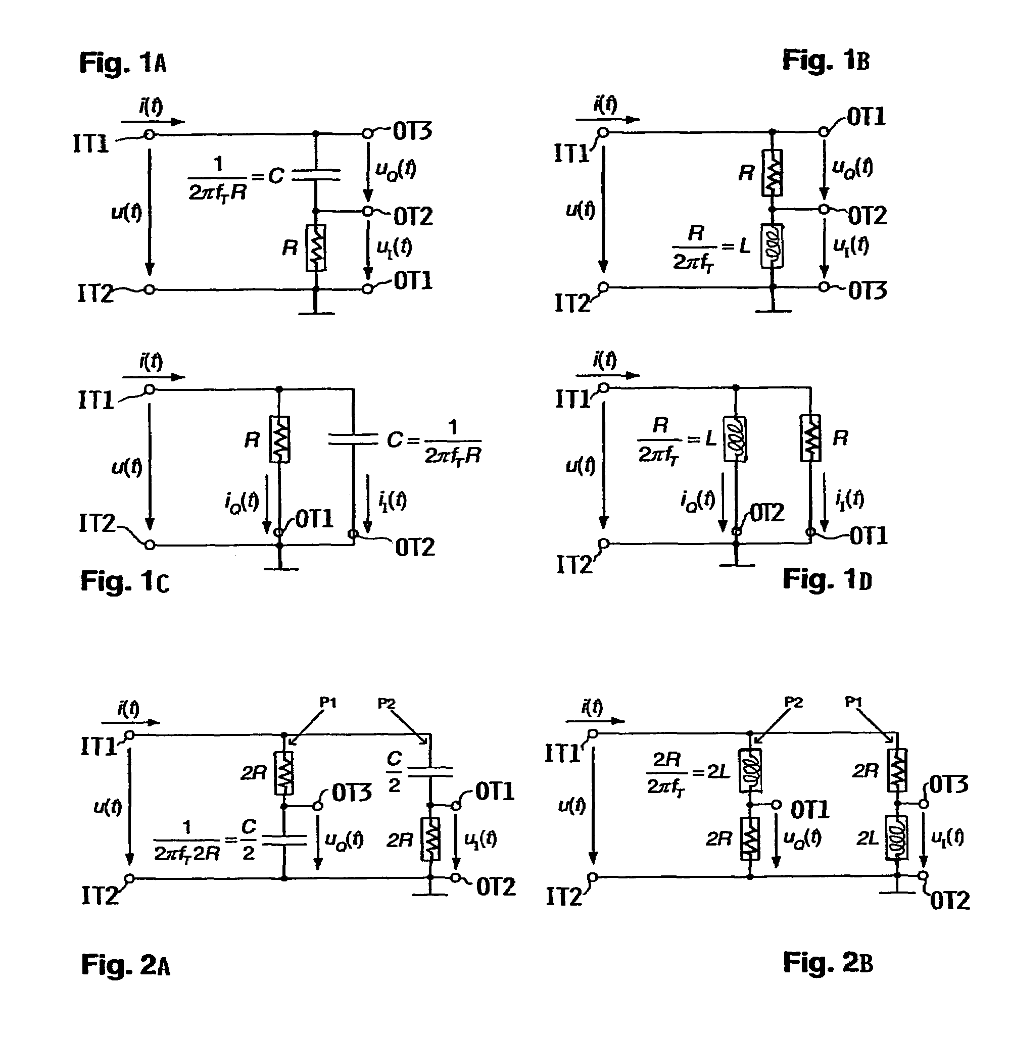
[0041]FIGS. 1A and 1B show the generation of an IQ-voltage signal for fT>0 by means of a series connection of ohmic resistance R and reactance C or L as well as tapping of the IQ-voltage signal, FIGS. 1C and 1D show the generation of an IQ-current signal by means of a parallel connection of ohmic resistance R and reactance C or L as well as tapping of the IQ-current signal.

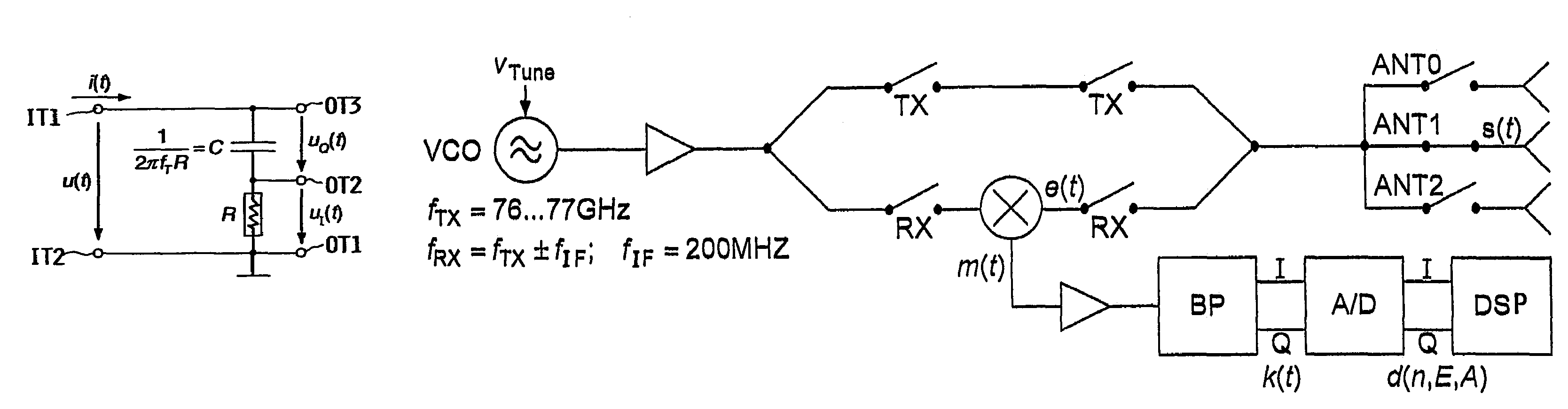
[0042]Consequently, an electric input signal with voltage u(t) and / or current i(t) is applied to a first input terminal IT1 relative to a second input terminal IT2, which is connected to a reference potential or particularly grounded (⊥) in this example. The input signal varies about a carrier frequency fT and in comparison with the carrier frequency is preferably narrow-band. Starting from a carrier frequency of 200 MHz a useful signal bandwidth of 25 kHz is used in an application considered in detail below, without significant interference occurring due to the slightly deviating amplitude.

[0043]The input signal ...


PUM


Abstract

Circuits generate an IQ voltage or current signal having orthogonal I- and Q-parts of approximately equal amplitude from an electric input signal having a frequency varying slightly around a carrier frequency, without needing a complex mixer. The circuit includes at least one ohmic resistance and at least one reactance connected in series (for a voltage) or in parallel (for a current). The reactance has an impedance at the carrier frequency approximately matching the resistance value of the ohmic resistance. The I- and Q-parts of the voltage signal are tapped as voltage drops across the resistance and the reactance. With two such series circuit branches in parallel, both voltage signal parts can be referenced directly to a reference potential, e.g. ground. The I- and Q-parts of the current signal are tapped as currents flowing through the resistance and the reactance. The circuit can be integrated at the output of a bandpass filter.

Description

CROSS-REFERENCE TO RELATED APPLICATIONS[0001]This application is a Continuation under 35 U.S.C. §111, 120 and §365 of PCT International Application PCT / DE03 / 02051, filed on Jun. 18, 2003, which designated the United States, and which was published in a language other than English. The entire disclosure of the PCT International Application is incorporated herein by reference. Also, this application is related to U.S. applications Ser. Nos. 11 / 018,813 and 11 / 018,865, both filed on Dec. 20, 2004.PRIORITY CLAIM[0002]Through the above identified PCT International Application, this application claims the priority under 35 U.S.C. §119 of German Patent Application 102 50 607.8, filed on Jun. 18, 2002. The entire disclosure of the German Priority Application is incorporated herein by reference.FIELD OF THE INVENTION[0003]The invention relates to a circuit arrangement for generating an IQ-signal consisting of mutually orthogonal I- and Q-parts having approximately equal amplitudes from an ele...

Claims


Application Information

Patent Timeline
Patent Type & Authority Patents(United States)
IPC IPC(8): H04B1/26H02M7/00H03H7/21
CPCH03H7/21
Inventor WINTERMANTEL, MARKUS
Owner A D C AUTOMOTIVE DISTANCE CONT
Why Eureka
Try Eureka