Storage system, a method of file data backup and method of copying of file data

a storage system and file data technology, applied in data processing applications, instruments, fault response, etc., can solve the problems of difficult sharing of drives, complex system maintenance and management, and large increase in maintenance and management costs of storage systems, so as to reduce the total capacity of hard disk drives and reduce the tco of storage systems.

Inactive Publication Date: 2007-09-25
HITACHI LTD
View PDF39 Cites 25 Cited by
  • Summary
  • Abstract
  • Description
  • Claims
  • Application Information

AI Technical Summary

Benefits of technology

[0022]An object of the present invention is to provide a storage system wherein the total capacity of hard disk drives can be used effectively and the management thereof is easy to reduce the TCO of the storage system.
[0023]More specifically, another object of the present invention is to allow the total capacity of hard disk drives to be used effectively and the management thereof is simplified in environment where a storage system for storing block-basis data, typically, a disk array system, coexists with a storage system for storing file-basis data, typically, a NAS. Yet another object of the present invention is to provide storage systems between which backing up and copying of file-basis data is performed at high speed.

Problems solved by technology

With the explosive increase of data amount, the cost required for maintaining and managing storage systems increases significantly.
In such environment where different types of systems exist separately, system maintenance and management will become complex.
However, it is difficult to share the drives because they were conventionally separate systems.
Consequently, the NAS is slow data backup and copy speed in comparison with storage systems such as disk array systems that directly transmit and receive block-basis data between them without the intervention of the file systems.

Method used


Image

  • Storage system, a method of file data backup and method of copying of file data
  • Storage system, a method of file data backup and method of copying of file data
  • Storage system, a method of file data backup and method of copying of file data

Examples


embodiment 1

[0051]A preferred Embodiment 1 of the present invention is depicted in FIGS. 1, 4, and 7.

[0052]A storage system of Embodiment 1 operates under the assumption that its storage areas are managed in units of logical volumes. Other embodiments are also subject to this assumption.

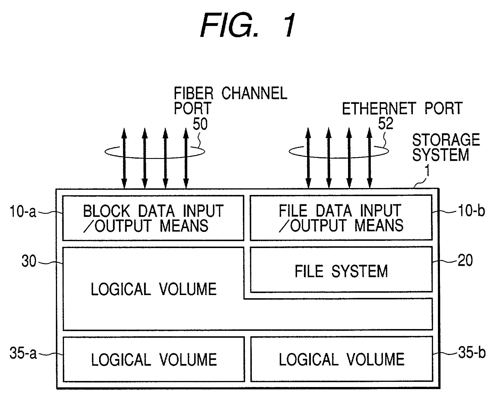
[0053]FIG. 1 shows the storage system 1 constructed in a logical structure.

[0054]The storage system 1 includes four fiber channel ports 50, four Ethernet channel ports 52, a block data input / output means 10-a, a file data input / output means 10-b, a logical volume management means 30, a file system 20, and logical volumes 35-a and 35-b.

[0055]Under the control of the logical volume management means 30, the logical volumes 35-a and 35-b taking the physical addresses of a plurality of hard disk drives and the logical volume management means 30 manages the storage areas on the plurality of hard disk drives. The logical volume management means 30 internally maintains a table that maps the addresses of the logical vol...

embodiment 2

[0108]A preferred Embodiment 2 of the present invention is depicted in FIGS. 5 and 8.

[0109]A storage system of Embodiment 2 also operates under the assumption that its storage areas are managed in units of logical volumes. Other embodiments are also subject to this assumption.

[0110]FIG. 5 shows the storage system 1 constructed according to another logical structure.

[0111]The logical structure of the storage system 1 shown in FIG. 5 is the same as the one of Embodiment 1 shown in FIG. 1 except that the block data input / output means 10-a and file the data input / output means 10-b are integrated into a single block data and file data input / output means, and the system has four Ethernet ports 54-a for block data and four Ethernet ports 54-b for file data.

[0112]Instead of the Ethernet ports, other types of ports that enable input / output of Internet Protocol compliant packets may be used.

[0113]FIG. 8 shows one example of the basic, actual configuration of the storage system of logical stru...

embodiment 3

[0141]Another preferred Embodiment 3 of the present invention is depicted in FIGS. 6 and 13.

[0142]A storage system of Embodiment 3 also operates under the assumption that its storage areas are managed in units of logical volumes. Other embodiments are also subject to this assumption.

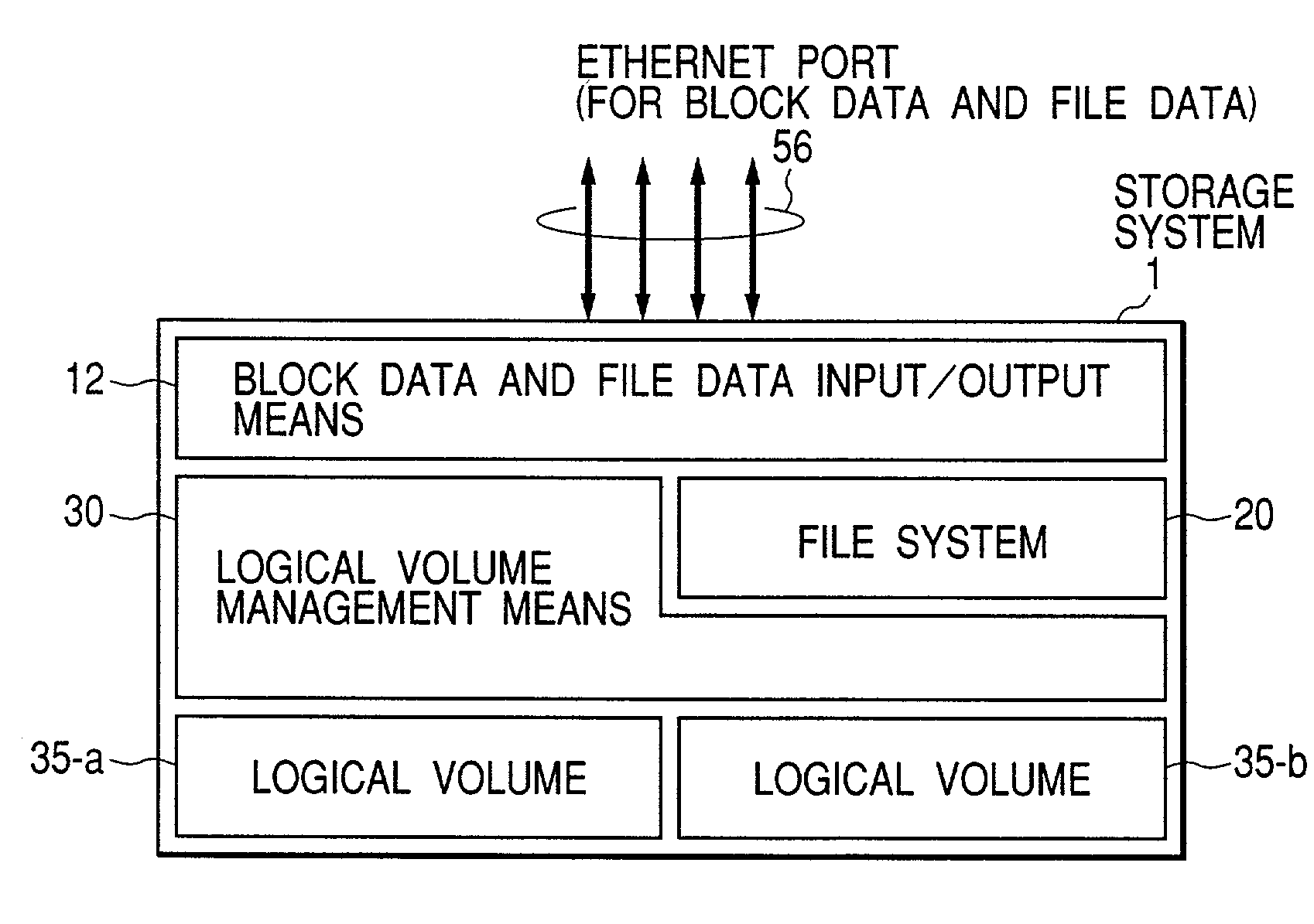
[0143]FIG. 6 shows the storage system 1 constructed in yet another logical structure.

[0144]The logical structure of the storage system 1 shown in FIG. 6 is the same as the one of Embodiment 2 shown in FIG. 5 except that the system has four Ethernet ports 56 which are common for block data and file data.

[0145]Instead of the Ethernet ports, other types of ports that enable input / output of Internet Protocol compliant packets may be used.

[0146]FIG. 13 shows one example of the basic, actual configuration of the storage system of logical structure shown in FIG. 6.

[0147]The storage system 1 includes one IP (Internet Protocol) switch 46 with four Ethernet ports 56 which are common for block data and file data, f...


PUM


Abstract

A storage system manages the total capacity of a shared storage medium to store block-basis data and file-basis data. When block data and its address are input through a fiber channel port, an inputloutput unit converts its data format to a data format that is internally applied by the storage system. When file data and its address are input, a file system converts its data format to a block data format internally applied by the storage system. The file system derives a file logical volume address from the received file address and translates file data to block data. A managing unit derives the address of a block logical volume from the block address delivered from the input / output unit. The managing unit translates block logical volume address or the file logical volume address to a physical address, and writes data to or reads data from the shared storage medium.

Description

BACKGROUND OF THE INVENTION[0001]1. Field of the Invention[0002]The present invention relates to a storage system for storing data on hard disk drives. More specifically, the present invention relates to a storage system for inputting / outputting block-basis data as well as file-basis data.[0003]2. Description of Related Art[0004]In the current information-oriented society, with the prevalence of inter-corporate electronic commerce by using the Internet and inter-corporate links, typically, supply chain management, making good use of data is important in corporate strategy.[0005]Storage systems for storing information facilitate IT platforms connection and operation.[0006]With the explosive increase of data amount, the cost required for maintaining and managing storage systems increases significantly.[0007]Corporations tend to gather storage systems and servers connected thereto in a data center, apply centralized management of databases such that kinds of servers can access to the d...

Claims


Application Information

Patent Timeline
Patent Type & Authority Patents(United States)
IPC IPC(8): G06F17/30G06F12/16G06F3/06G06F7/00G06F11/14G06F12/00
CPCG06F3/0607G06F3/0661G06F3/067G06F11/1435Y10S707/99931Y10S707/959
Inventor FUJIMOTO, KAZUHISA
Owner HITACHI LTD
Why Eureka
Try Eureka