Pigging ball valve

a technology of pigging ball valve and valve body, which is applied in the direction of valve details, plug valves, multiple-way valves, etc., can solve the problems that the pigging ball valve is a continuing challeng

Active Publication Date: 2007-10-02
ARGUS MACHINE
View PDF33 Cites 27 Cited by
  • Summary
  • Abstract
  • Description
  • Claims
  • Application Information

AI Technical Summary

Problems solved by technology

The design of pigging ball valves is a continuing challenge for engineers.

Method used


Image

  • Pigging ball valve
  • Pigging ball valve
  • Pigging ball valve

Examples


Embodiment Construction

[0008]In this patent document, “comprising” means “including” and does not exclude other elements being present. In addition, a reference to an element by the indefinite article “a” does not exclude the possibility that more than one of the elements is present.

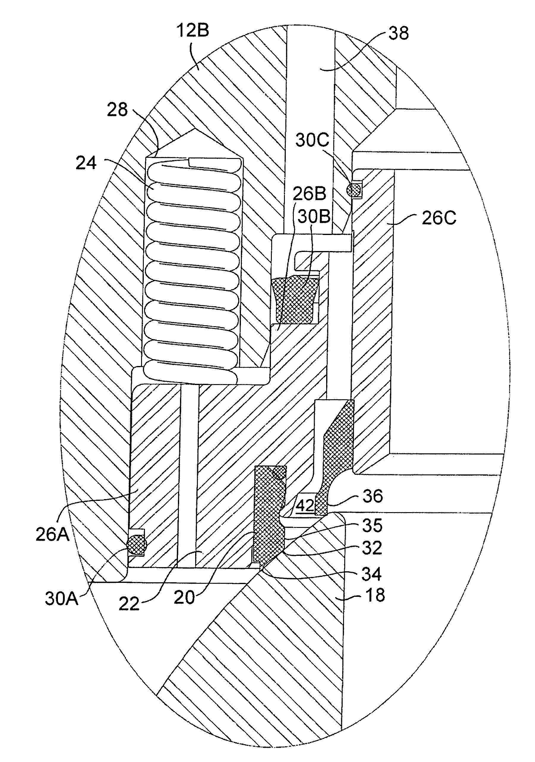
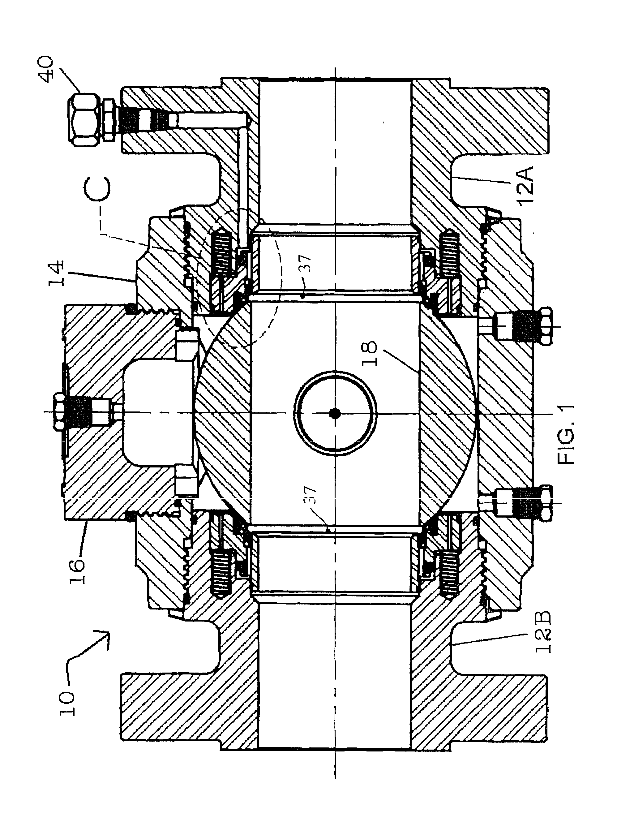
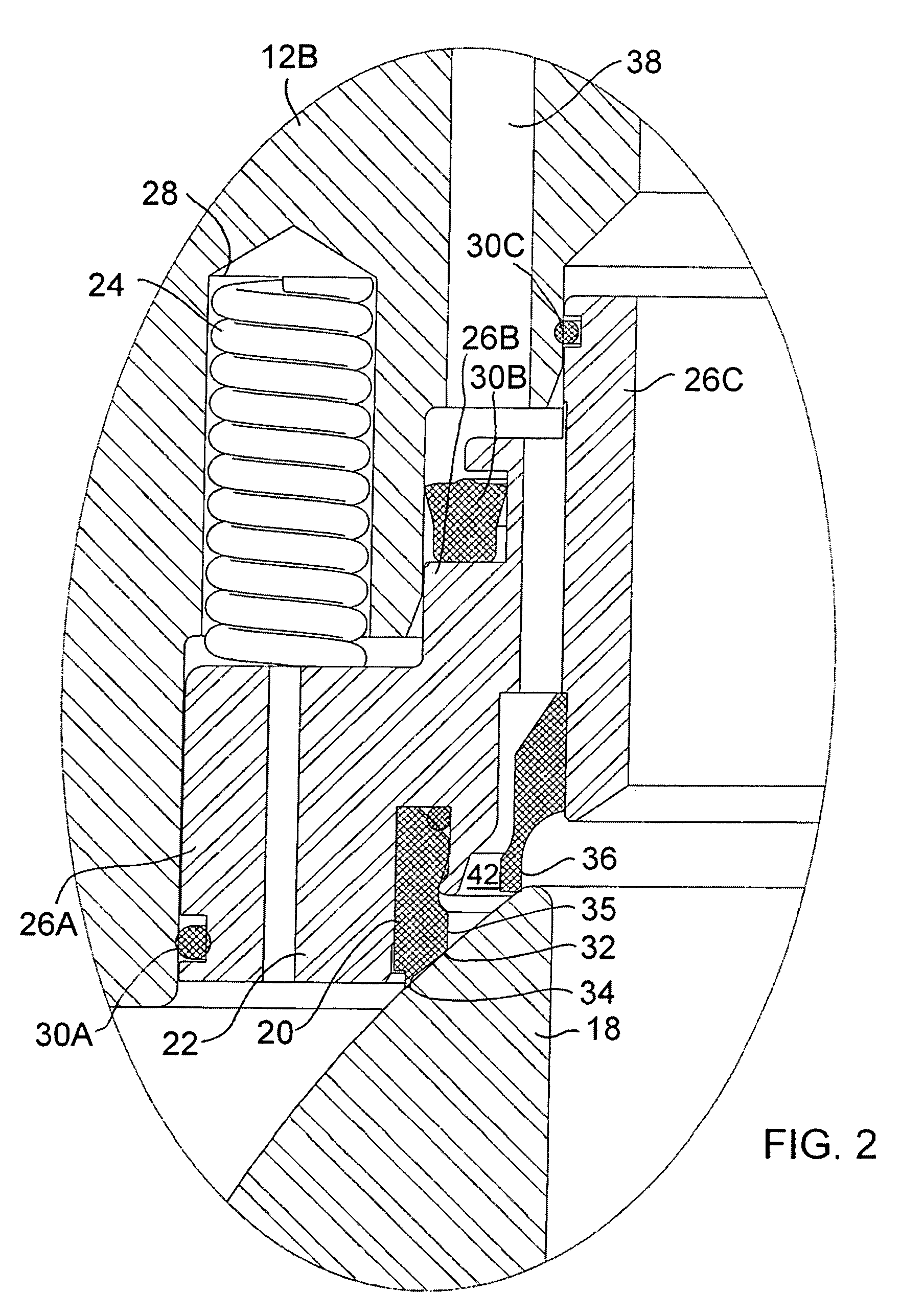
[0009]Referring to FIG. 1, the main components of a pigging ball valve 10 are a housing 12 formed of two tailpieces 12A and12B, a central portion 14, in which the tailpieces 12A and 12B are threaded, an entry port plugged with entry plug 16 on one side of the housing 12 and a ball core 18. Removal of the entry plug 16 provides for insertion of a pig (not shown) into a pipeline (not shown) or removal of the pig from the pipeline through the entry port. The flanged ends of the tailpieces 12A and 12B typically bolt to corresponding flanges of the pipeline. The ball core 18 is mounted for rotation within the housing 12 between a position for transferring a pig to and from the entry port and a position for transferring the pig to a...


PUM


Abstract

A pigging ball valve with a housing and ball core supported for rotation within the housing. The ball core sits on a valve seat, which is supported by a seat carrier. The valve seat carrier has three distinct diameters that locate the seat in the housing and thus provides an anti-cocking feature. A seat insert has a pressure sealing surface and wiper lip on the outer diameter of the pressure sealing surface. An internal seat deflector ring is provided inside of the pressure sealing surface. The seat carrier is spring loaded.

Description

[0001]This application claims priority of Canadian Application No. 2,480,501 filed Sep. 28, 2004, and entitled “PIGGING BALL VALVE”, which is hereby incorporated by reference.BACKGROUND OF THE INVENTION[0002]Pigs are round or cylindrical objects used for cleaning pipelines. The pigs are introduced into the pipeline through a pigging ball valve and carried by fluid pressure through the pipeline to an extraction point, usually another pigging ball valve. The pigging ball valves must be carefully designed to allow introduction or removal of the pig without a risk of release of high pressure fluids from the pipeline, either during introduction or removal of the pig or while the pigging ball valve is not being used. In addition, the pigging ball valves must be durable and easy to use. The design of pigging ball valves is a continuing challenge for engineers.SUMMARY OF THE INVENTION[0003]According to an aspect of the invention, there is provided an improved pigging ball valve with a housi...

Claims


Application Information

Patent Timeline
Patent Type & Authority Patents(United States)
IPC IPC(8): F16K25/02
CPCF16K5/201F16K27/067F16K5/227Y10T137/86871Y10T137/86863
Inventor BAZIN, ALLANWILTERMUTH, RANDY
Owner ARGUS MACHINE
Why Eureka
Try Eureka