[0011]Accordingly, it is an object of the present invention to overcome these and other drawbacks of the prior art by providing novel methods and devices for managing / improving the fluid flow characteristics in wells, risers and hilly
terrain pipelines of oil, gas or condensate (cumulatively referred to here as petroleum) well systems by provision of an alternate tubular pathway for producing reservoir fluids that is internally reconfigured to affect the gas-liquid flow dynamics through the conduit / pipeline / riser / well, whereby the
carrier phase (gas) more efficiently transports the carried phase (liquids or solids). To maintain and repair wells, risers and pipelines throughout
subsea and land-based well
production tubing systems, it is important to have access from the surface for
pigging,
fishing or
coiled tubing operations and for land-based pipelines to have access end-to-end for pigging operations. The requirement of maintaining a sufficiently large pipeline / riser / well tubing
diameter for such access precludes alteration in the design of the
pipe itself as anticipated by the invention, thereby making it necessary to provide an
alternate pathway.
[0012]Further, it is an object of the present invention to improve the flow characteristics in such alternate production wells, risers or hilly
terrain pipelines of oil, gas or condensate wells by subdividing the flow into a plurality of individual fluid flows through substitution of an open pipe / conduit with one having a plurality of smaller parallel channels such as pipes placed inside, each such parallel pipe having a smaller cross-sectional area than the single open pipe, and preferably round inside. By virtue of reducing the
diameter of the flow channel, the
gas phase is less likely to slip past the
liquid phase, thereby forcing an increase in the transfer of energy from the gas (
carrier phase) to the liquid (carried phase), resulting in a lower producing gas-
liquid ratio (GLR) downstream.
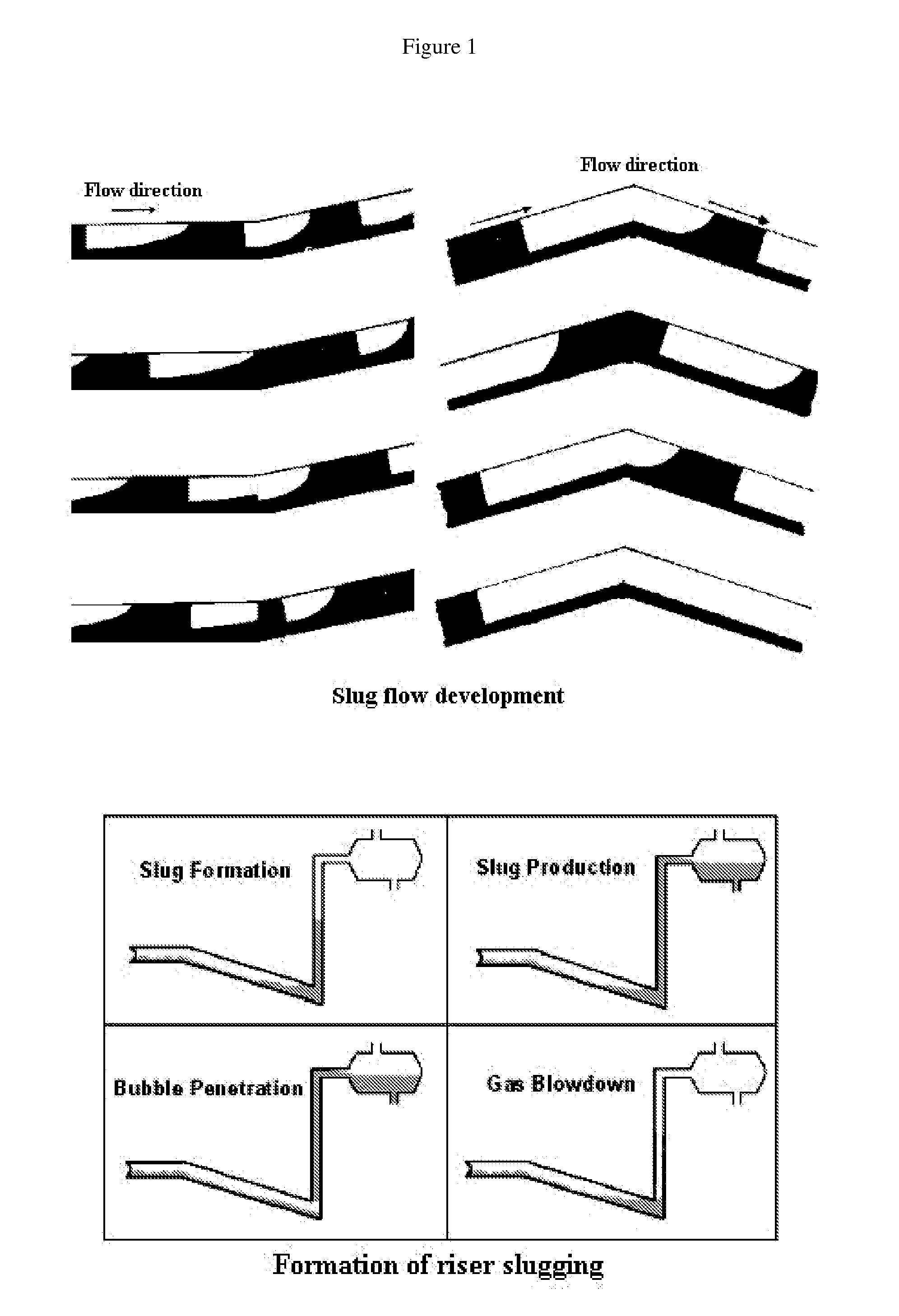
[0013]Further, it is an object of the present invention to improve the flow characteristics in wells, risers or hilly terrain pipelines of petroleum wells by virtually eliminating liquid slugging by way of dividing the flow into a plurality of smaller cross-section flows. Liquid
slug length is highly correlated with the
diameter of the flow pipeline, with smaller diameter pipes producing shorter liquid slugs, and so the invention will result in a smaller average length /
mass for each
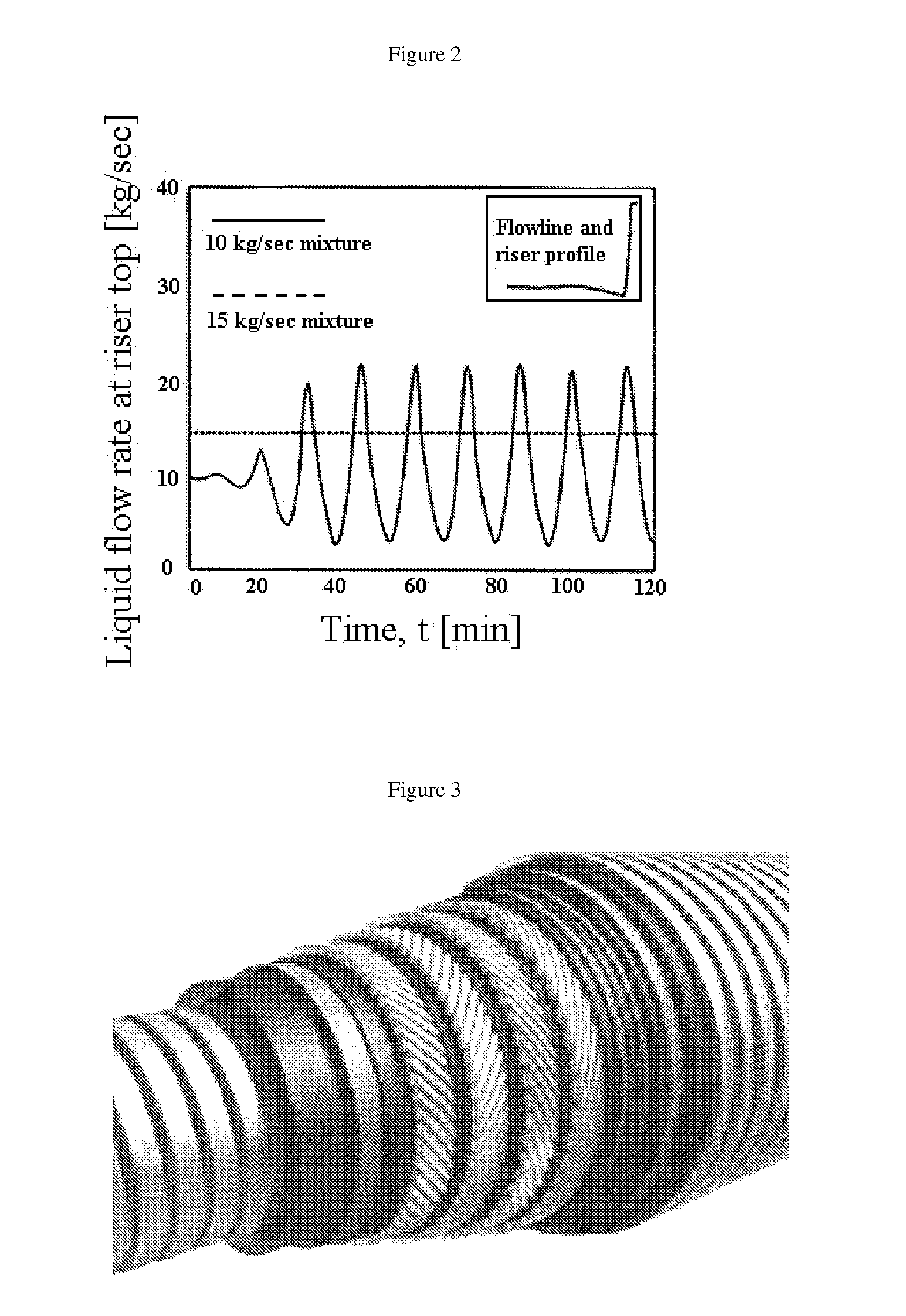
slug. Second, such smaller liquid slugs from such plurality of parallel small riser columns arriving at the subsurface / surface facilities will each arrive independently. Greater number of independent pipes / tubes / flows causes a greater tendency to statistical averaging of the flow volume /
mass exiting the riser at any given moment. This in turn reduces the potential for any single large liquid slug to arrive at the surface facilities. Third, a preferred design uses relatively small diameter (6 to 25 mm) internal pipes as compared to the 4- to 6-inch diameter pipes commonly used in practice. The flow through these small pipes will have the annular flow regime toward the top of the column and in a significant proportion down its length, given the effect of containment by virtue of the small diameter pipes. As the proportion of gas in the flow increases when more gas comes out of solution with increased elevation / distance (lower pressure) and as the
gas phase expands with declining pressure (eventually resulting in annular flow), the recombined flow at the surface has a steady-state nature and therefore will not damage the surface facilities (separators, slug catcher, pipes, etc.).
[0014]Further, it is an object of the present invention to provide the capability to adjust the volumetric characteristics of the
subsea production system over the life of the well to accommodate the reduced flow conditions experienced as reservoir depletion ensues. Early in the life of a gas-driven
oil well for example, a large diameter pipe is beneficial to maximize production (
high pressure and flux). But in lower flow rate conditions, as the
gas phase void fraction increases throughout the system (and increasingly so downstream), decreasing the diameter of the production pipe increases the liquid proportion of the produced fluid (e.g. conversion to a smaller-diameter “velocity string” or “macaroni tubing” later in the life of an
oil well to increase liquid production). The riser of the present invention, having a plurality of parallel small diameter pipes, is designed to be capable of being changed / replaced over the life of the well, substituting the one with a smaller diameter pipes (to increase transporting efficiency of
free gas phase) or fewer pipes (adjust for less gas-liquid flux) over time to better optimize liquid production while minimizing gas production. In this
vein, a subsea manifold connecting multiple wells to the entrance of multiple parallel high-efficiency risers of the invention, each such riser having a plurality of parallel small cross-section tubes / conduits inside, and the number of risers permitted to flow at any given time can be varied using valve control means based on the volume of the combined production of the wells, which is expected to vary over time. In this case, such dual pathway riser of the invention consists of more than one parallel valve-controlled riser / conduit having multiple parallel smaller-diameter internal passageways (in effect, a “multiple-pathway riser”). As such, the volumetric characteristics of the parallel riser system can be optimized over the life of the well(s) to maximize liquid production and to minimize the volume of gas or pressure differential needed to produce it, maximizing reservoir depletion.

