Lightning protection system for composite structure

a composite structure and protection system technology, applied in the field of protecting composite structures, can solve the problems of increasing removal difficulty, and achieve the effects of improving safety, reducing maintenance costs, and improving safety

Active Publication Date: 2007-10-02
THE BOEING CO
View PDF3 Cites 110 Cited by
  • Summary
  • Abstract
  • Description
  • Claims
  • Application Information

AI Technical Summary

Benefits of technology

[0011]Advantageously, a preferred lightning protection appliqué provides flexibility in lightning protection design without increasing aircraft weight appreciably and with superior performance and protection. Appliqué dielectric and conductor layers are simply sequentially pressed in place on the skin to avoid adding an embedded conductive layer or requiring a conductive surface protection layer for a CFRP skin. Thus a preferred lightning protection system simplifies aircraft skin design while reducing weight. In addition to weight, cost savings are realized from simple dielectric and conductor layer manufacturing requirements, as well as maintenance simplicity. Although age may make removal increasingly difficult, an entire preferred appliqué may be replaced by peeling the old ply(plies) off and pressing a new one(s) in place.

Problems solved by technology

Although age may make removal increasingly difficult, an entire preferred appliqué may be replaced by peeling the old ply(plies) off and pressing a new one(s) in place.

Method used


Image

  • Lightning protection system for composite structure
  • Lightning protection system for composite structure
  • Lightning protection system for composite structure

Examples


Embodiment Construction

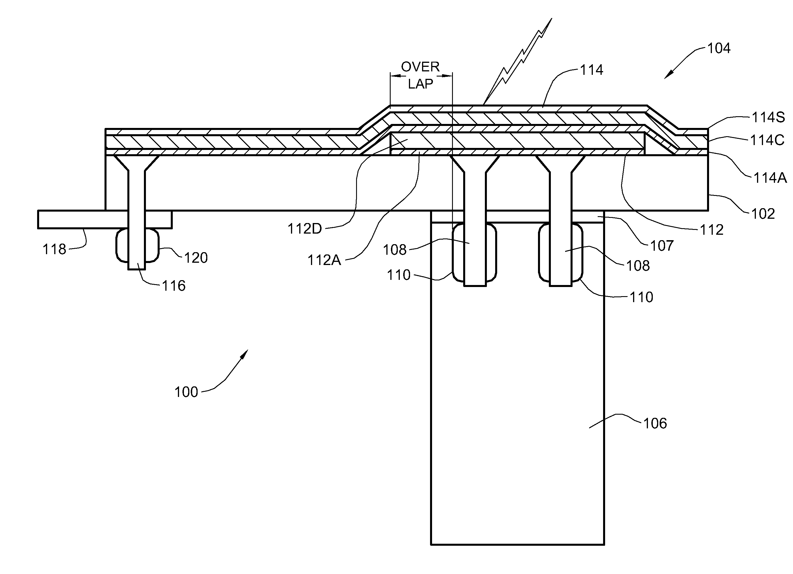
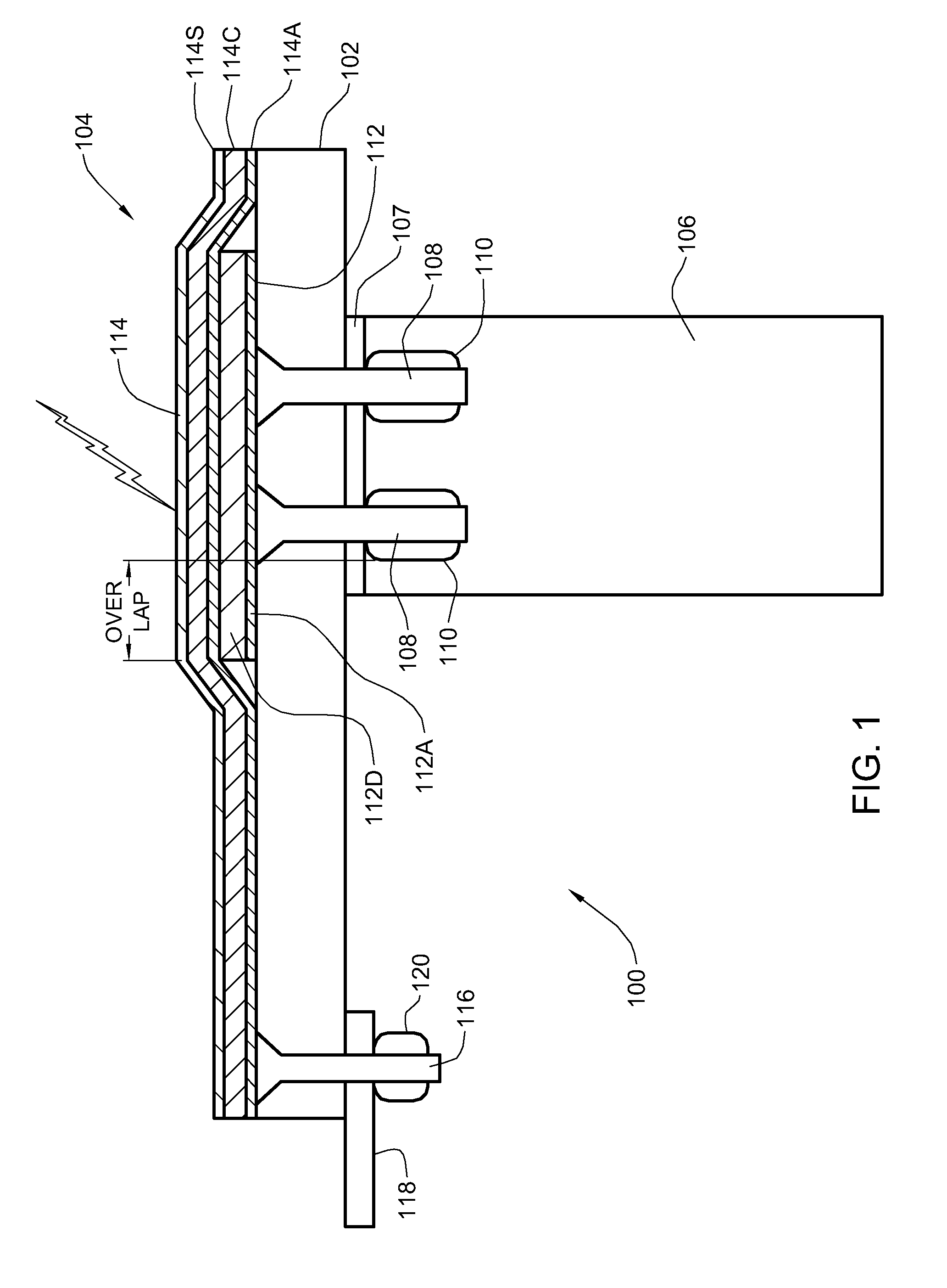
[0015]Turning now to the drawings and more particularly, FIG. 1 shows an example of a lightning protection system according to a advantageous embodiment of the present invention in a cross section 100 of an aircraft. In this example, the cross section 100 is taken through the composite skin 102, e.g., a Carbon Fiber Reinforced Plastic (CFRP) skin, of the aircraft wing, protected by a preferred embodiment Lightning Protection Appliqué (LPA) 104. The composite skin 102 is fastened to a rib (metal or CFRP) 106 or similarly to a spar (CFRP), by skin fasteners 108 extending through the skin 102 and shear tie flange 107, held in place by collars or nuts 110. In this example, the cross section 100 is part of a fuel tank of a wing section. Although shown in this example protecting skin fasteners 108 at a wing fuel tank, this is for example only. A preferred LPA 104 may be used to protect any composite structure surface area where metal is exposed at the skin surface and so, is exposed to si...


PUM


Abstract

A lightning protection system for protecting composite structures and a method of protecting composite structures from lightning strikes. A dielectric ply is fixed above and completely covers metal surface features, e.g., skin fasteners through a composite skin to a wing fuel tank. A conductive ply is fixed above and completely covers the dielectric ply and extends to an external connection to a platform ground. The conductive ply directs current from lightning strikes away from metal surface features, e.g., to the platform ground. Both plies may be adhesively backed and sequentially pressed into place.

Description

CROSS REFERENCE TO RELATED APPLICATION[0001]The present invention is related to Published U.S. Patent Application No. 20050181203, entitled “Appliqué” to Diane C. Rawlings et al., assigned to the assignee of the present invention.BACKGROUND OF THE INVENTION[0002]1. Field of the Invention[0003]The present invention generally relates to protecting composite structures from lightning strikes, and more particularly, to an appliqué for protecting composite aircraft from lightning strikes.[0004]2. Background Description[0005]Since aluminum and other metals are highly conductive, a transient charge from a lightning striking a metal body discharges into the metal body with current from the discharge being distributed relatively evenly over the body. So, a typical lightning strike to a metal aircraft causes no or only minor damage to aircraft components. However, carbon fiber composites generally have a higher strength-to-weight ratio than aluminum, and so, are increasingly replacing aluminu...

Claims


Application Information

Patent Timeline
Patent Type & Authority Patents(United States)
IPC IPC(8): H05F3/00
CPCB64D45/02
Inventor LE, QUYNHGIAO N.MURAKAMI, RONSTEELE, ERIC R.KIRCHNER, JAMES F.
Owner THE BOEING CO
Why Eureka
Try Eureka