Capturing a user's design intent with resolvable objects

a technology of user design and object, applied in the field of user design intent capture, can solve the problems of design being physically impossible or impractical, roof or ceiling collapse, and inefficiency,

Active Publication Date: 2007-10-02
ARMSTRONG WORLD IND INC
View PDF13 Cites 30 Cited by
  • Summary
  • Abstract
  • Description
  • Claims
  • Application Information

AI Technical Summary

Problems solved by technology

For example, one typical software design program might allow an architect to design a roof or ceiling that is ill-suited for the number or type of weight-bearing walls the architect has presently drawn.
If the roof were actually constructed as designed by the architect, the roof or ceiling might collapse.
In a situation such as this, however, the builder might indicate to the architect that the design is physically impossible or impractical, and ask for a redesign.
This, of course, can lead to any number of inefficiencies.
Part of the problem with many design software programs that can lead to designing physically impractical structures is the notion that many such design problems require some drawing of a space in flat, two-dimensional space.
While three-dimensional rendering is available in some design software, three-dimensional rendering is fairly processing or resource intensive, and can take an additional amount of time.
Furthermore, while three-dimensional rendering does allow the designer to “travel” around a design, such as an office, conventional three-dimensional rendering in design software does not typically allow the designer to peek around doors, look under tables, travel through hallways, or look up at ceilings, and the like very effectively.
Three-dimensional design software also does not ordinarily accurately capture other natural variables that might affect the positioning of lamps, desks, or computer monitors based on the directly or spread of available natural light, and so on.
In addition, neither the three-dimensional rendering nor the two-dimensional drawing views are designed to accommodate necessary modifications to the objects or walls, based on real-world materials, or other important constraints.
Unfortunately, there is generally not a convenient way for an accurate parts list to be generated automatically from one or more design views.
Although there are some software programs that can produce parts lists from generated view, the parts lists are not always accurate.
For example, in the case where two L-shaped desks will be adjoined in a work space, a conventional parts list that interfaces with the design software will not ordinarily be able to deduce the correct, specific amount of parts needed for each environment, such as in the case of shared components.
Furthermore, the parts lists that are generated are difficult to read, and usually comprise some detailed information in text, or in a stock keeping unit (“SKU”), and do not readily inform the reader exactly what the image looks like.
Thus, conventional, automatically generated parts lists must often be edited in painstaking fashion before they can be submitted to an order fulfillment company.

Method used


Image

  • Capturing a user's design intent with resolvable objects
  • Capturing a user's design intent with resolvable objects
  • Capturing a user's design intent with resolvable objects

Examples


Embodiment Construction

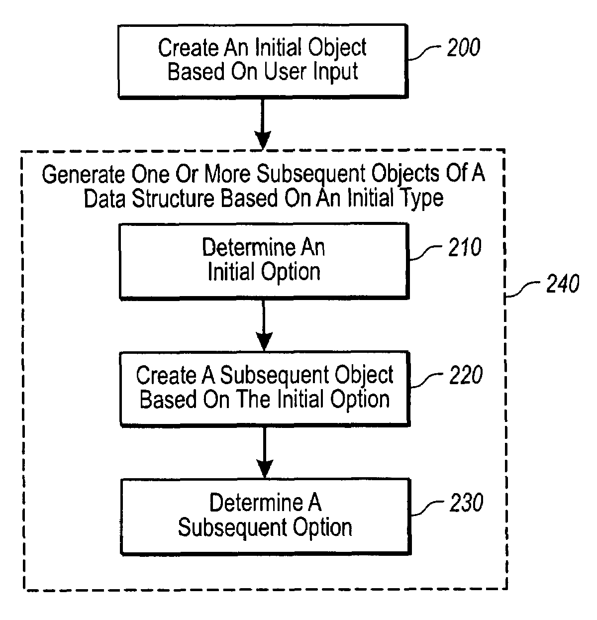
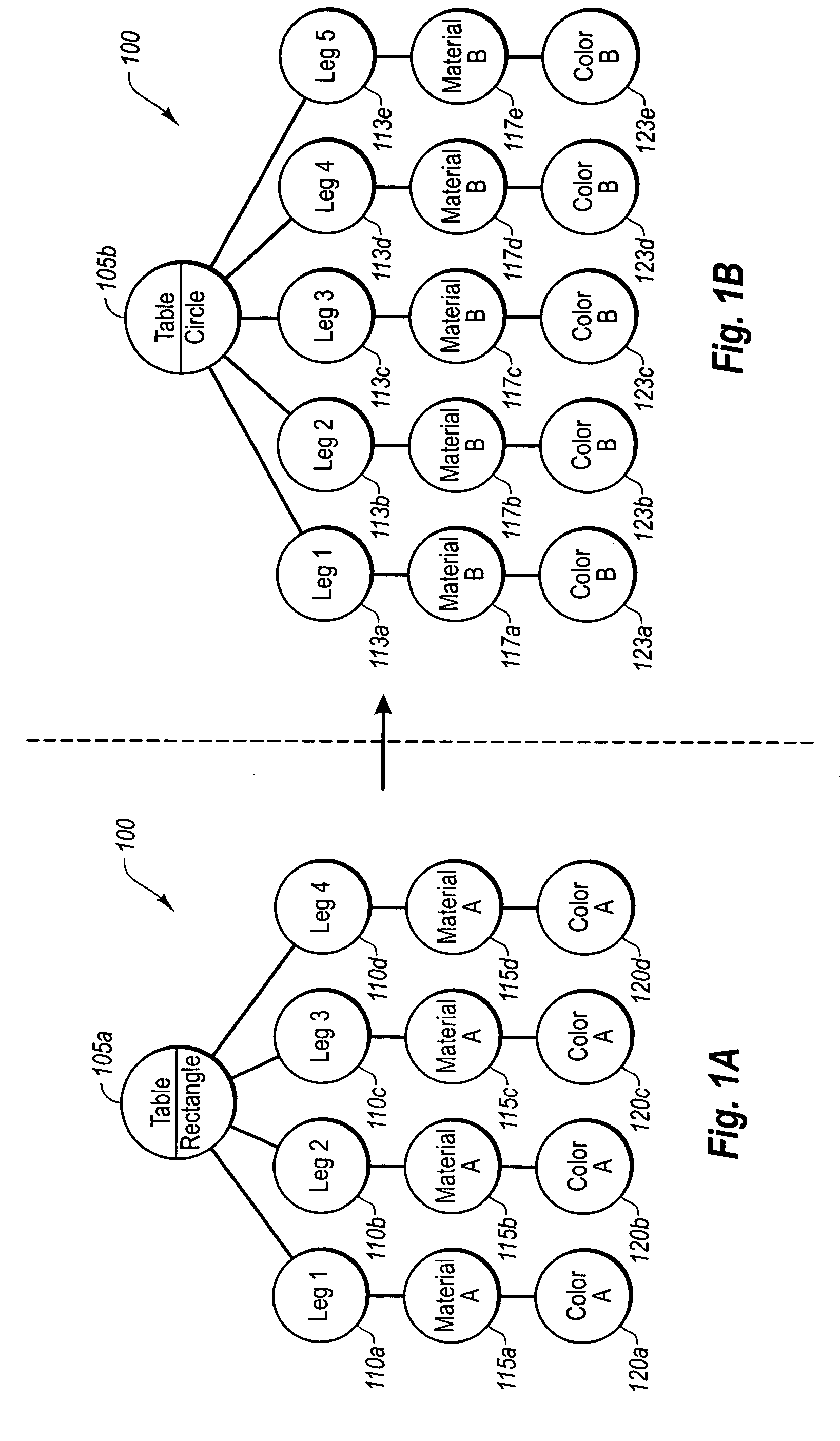
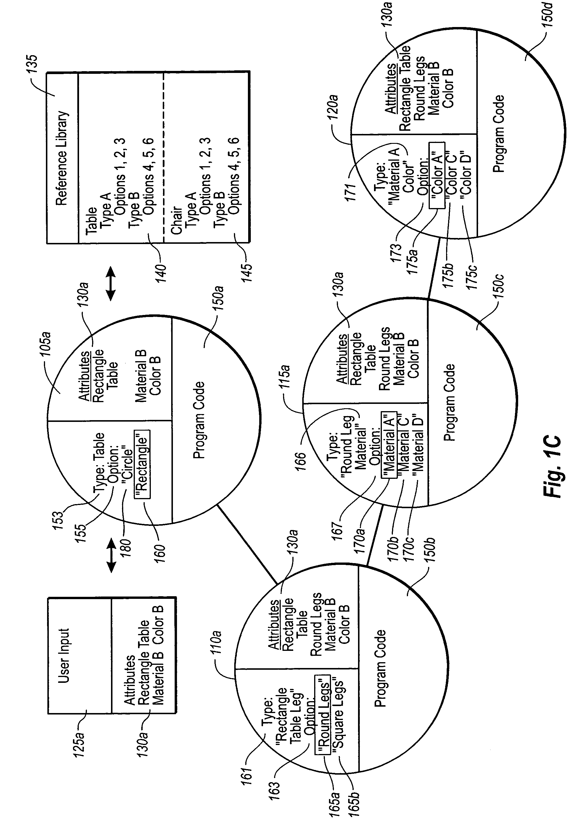
[0027]The present invention extends to systems, methods, and computer program products configured to automatically resolve a user's design choices in real time. In particular, implementations of the present invention relate to the creation of program objects in response to user input, where the program objects are configured to continually and automatically resolve a user's design choices in real-time and in consideration of real-world scenarios.

[0028]For example, as will be understood from the present description and claims, one aspect of the invention relates to associating user input with a software object that includes type and option components. Another aspect of the invention involves automatically creating child objects based on one or more selected option components of the prior parent object. Still another aspect of the invention relates to ensuring that user selections accord with real-world values in real-time, such as by implementing program code in each of the parent an...


PUM


Abstract

Software for designing interior and / or exterior spaces efficiently ensures that user intent is captured in a timely, practical manner. When a user creates an input, such as selecting a shape of a table to put into a design space, the design software creates an initial object that is managed as part of a data structure. Generally, the initial object includes a type element having one or more options. Program code in the created initial object determines an appropriate option based on any number of factors including, but not limited to, elements of the user's original input. A subsequent child object with a set of independent program code is also created, which has as its type the option determined from the previous initial object. The subsequent object also determines its options based on attributes of the user's input, and creates any additional child objects where appropriate.

Description

CROSS-REFERENCE TO RELATED APPLICATIONS[0001]The present invention claims the benefit of priority to U.S. Provisional Patent Application No. 60 / 602,233, filed on Aug. 17, 2004, entitled “Method and Apparatus for the Selection, Organization and Configuration of Products through Object Oriented Design Intent”, the entire contents of which are incorporated by reference herein.BACKGROUND OF THE INVENTION[0002]1. The Field of the Invention[0003]This invention relates to systems, methods, and computer program products for modeling the design of commercial and residential interiors, and related spaces.[0004]2. Background and Relevant Art[0005]As computerized systems have increased in popularity, so has the range of applications that incorporate computational technology. Computational technology now extends across a broad range of applications, including a wide range of productivity and entertainment software. Indeed, computational technology and related software can now be found in a wide ...

Claims


Application Information

Patent Timeline
Patent Type & Authority Patents(United States)
IPC IPC(8): G06F17/50
CPCG06T19/20G06T2219/2021G06T2219/2012
Inventor LOBERG, BARRIE ARNOLD
Owner ARMSTRONG WORLD IND INC
Why Eureka
Try Eureka