High switching frequency DC-DC converter with fast response time

a dc-dc converter and high switching frequency technology, applied in dc-dc conversion, power conversion systems, climate sustainability, etc., can solve the problem of slow load transient response times, and achieve the effect of saving printed circuit board area, slow load transient response times, and high switching frequency

Active Publication Date: 2007-10-09
ACTIVE SEMI
View PDF4 Cites 90 Cited by
  • Summary
  • Abstract
  • Description
  • Claims
  • Application Information

AI Technical Summary

Benefits of technology

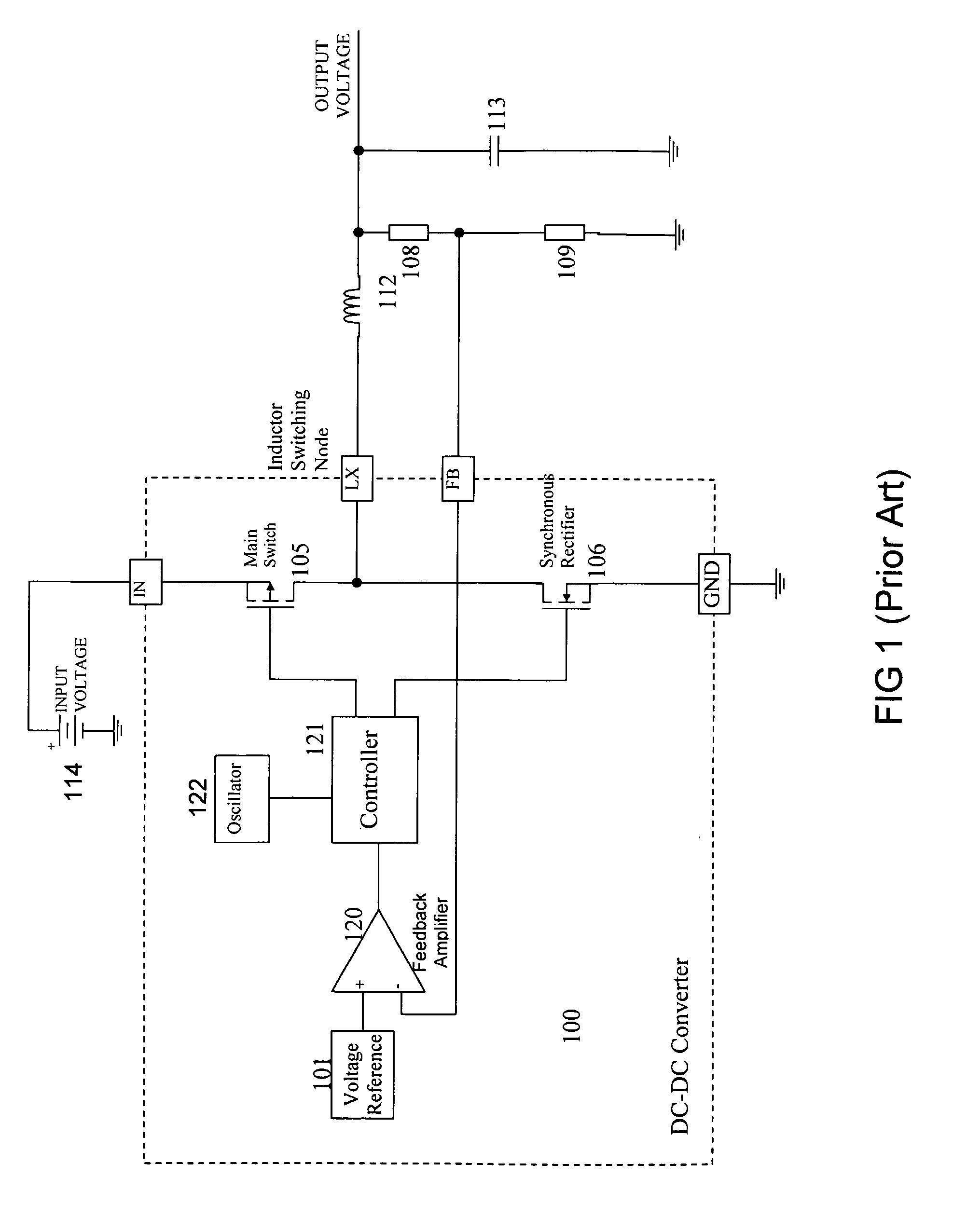
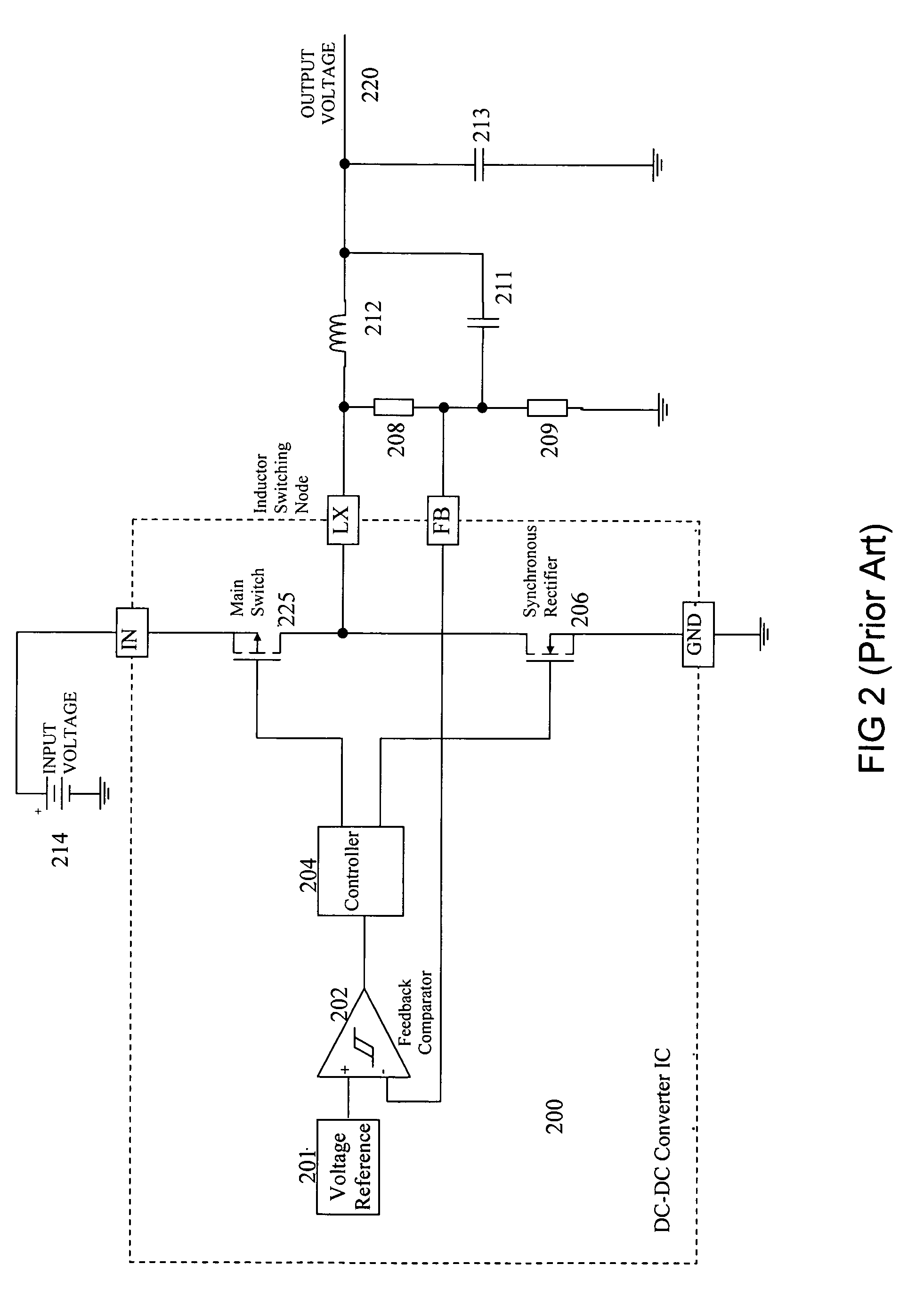
[0021]High switching frequency in DC-DC converters is desirable to enable the use of relatively small external components to thereby save printed circuit board area. However, using conventional methods to achieve high switching frequency typically imposes a limitation on duty cycle range due to response delays of the amplifying and comparison circuitry, which also slows load transient response times.
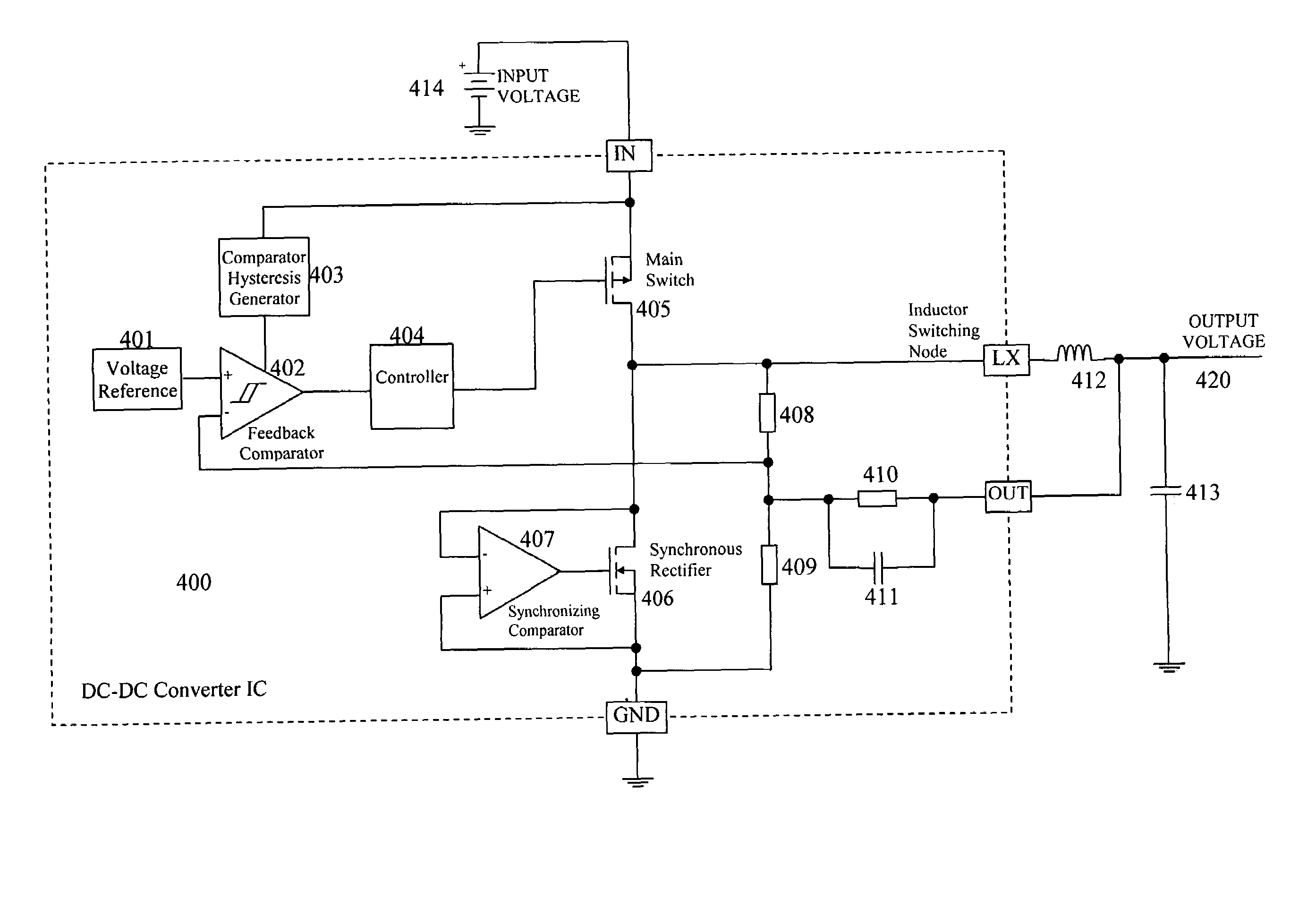
[0022]In one embodiment of the present invention, a hysteretic DC-DC converter is provided with high switching frequency, good load regulation, and fast load step response, and in which the switching frequency is externally adjustable by the feedback network and is essentially independent of duty cycle variation. This dc-dc converter embodiment has a feedback network that includes the following circuit nodes: a switching node; a converter output node; a ground node; and a feedback node; and, the following resistors: a resistor electrically coupled between the output node and the feedback node; a resistor electrically coupled between the switching node and the feedback node; and a resistor coupled between the feedback node and the ground node.

Problems solved by technology

However, using conventional methods to achieve high switching frequency typically imposes a limitation on duty cycle range due to response delays of the amplifying and comparison circuitry, which also slows load transient response times.

Method used


Image

  • High switching frequency DC-DC converter with fast response time
  • High switching frequency DC-DC converter with fast response time
  • High switching frequency DC-DC converter with fast response time

Examples


Embodiment Construction

[0028]The present invention is best understood by reference to the detailed figures and description set forth herein.

[0029]Embodiments of the invention are discussed below with reference to the Figures. However, those skilled in the art will readily appreciate that the detailed description given herein with respect to these figures is for explanatory purposes as the invention extends beyond these limited embodiments. For example, it should be appreciated that those skilled in the art will, in light of the teachings of the present invention, recognize a multiplicity of alternate and suitable approaches, depending upon the needs of the particular application, to implement the functionality of any given detail described herein, beyond the particular implementation choices in the following embodiments described and shown. That is, there are numerous modifications and variations of the invention that are too numerous to be listed but that all fit within the scope of the invention. Also, ...


PUM


Abstract

A hysteretic DC-DC converter is provided with high switching frequency, good load regulations, and fast load step response and in which the switching frequency is externally adjustable by a novel feedback network that enables substantial independence of duty cycle variation.

Description

CROSS-REFERENCE TO RELATED APPLICATIONS[0001]The present Utility patent application claims priority benefit of the U.S. provisional application for patent No. 60 / 691,456 filed on Jun. 16, 2005, under 35 U.S.C. 119(e).[0002]The contents of this related provisional application are incorporated herein by reference.FEDERALLY SPONSORED RESEARCH OR DEVELOPMENT[0003]Not applicable.REFERENCE TO SEQUENCE LISTING, A TABLE, OR A COMPUTER LISTING APPENDIX[0004]Not applicable.COPYRIGHT NOTICE[0005]A portion of the disclosure of this patent document contains material that is subject to copyright protection. The copyright owner has no objection to the facsimile reproduction by anyone or the patent document or, patent disclosure as it appears in the Patent and Trademark Office, patent file or records, but otherwise reserves all copyright rights whatsoever.FIELD OF THE INVENTION[0006]The present invention relates generally to the field of DC-DC conversion integrated circuits (ICs). More particularly...

Claims


Application Information

Patent Timeline
Patent Type & Authority Patents(United States)
IPC IPC(8): G05F1/40
CPCH02M3/1588Y02B70/1466Y02B70/10
Inventor GAN, GEHUYNH, STEVEN
Owner ACTIVE SEMI
Why Eureka
Try Eureka