Protection circuit for three-wire system current output transmitter

A technology for protecting circuits and transmitters, applied in the direction of emergency protection circuit devices, emergency protection circuit devices, circuit devices, etc. for limiting overcurrent/overvoltage, and can solve the problem of overcurrent damage to diode D2, diode D2 or load resistance Damage, poor current limiting effect and other problems, to achieve the effect of reasonable and practical circuit and reduce the area of ​​circuit board

Active Publication Date: 2010-03-10
KELI SENSING TECH NINGBO CO LTD
View PDF0 Cites 3 Cited by
  • Summary
  • Abstract
  • Description
  • Claims
  • Application Information

AI Technical Summary

Problems solved by technology

[0005] 1. The resistor R1 is introduced into the circuit for current limiting. If the resistance is too large, it will affect the load capacity. If the resistance is too small, the current limiting effect will be poor. Because the power is relatively large, the corresponding volume is relatively large, which is not conducive to the miniaturization of the product, so the resistor R1 is usually not used.
[0006] 2. When the positive terminal of the power supply is connected to figure 1 In the GND position, the negative terminal of the power supply is connected to figure 1 In the VCC position, the signal is terminated at figure 1 When the IOUT terminal is in the middle (power reverse connection phenomenon), the current flowing through the diode D2 and the resistor R1 is relatively large at this time, and if the detection resistor at the load terminal is relatively small, it may cause damage to the diode D2 or the load resistor
[0007] 3. When the power supply is positively connected at figure 1 In the GND position, the negative terminal of the power supply is connected to figure 1 In the IOUT position, the signal is terminated at figure 1 When the VCC terminal is in the middle, it is equivalent to a direct short circuit of the power supply (assuming that the resistance of the resistor R1 is small or not installed), resulting in overcurrent damage to the diode D2
[0008] Therefore, the traditional protection circuit has some irrationality and needs to be further improved.

Method used


Image

  • Protection circuit for three-wire system current output transmitter
  • Protection circuit for three-wire system current output transmitter

Examples


Embodiment Construction

[0021] The present invention will be further described in detail below in conjunction with the accompanying drawings and embodiments.

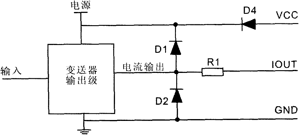
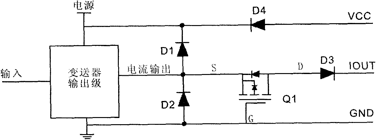
[0022] In view of the above deficiencies, the present invention can provide all-round protection for the power supply and output lines of the transmitter. The schematic diagram is shown in figure 2 .

[0023] In the technical solution of the present invention, a three-wire current output transmitter protection circuit includes clamping diodes D1 and D2, a diode D4 is connected between the power supply terminal and the transmitter terminal of the VCC terminal to prevent reverse connection of the power supply. The key point of the invention is to remove the current limiting resistor and replace it with a P-channel enhanced small-signal MOS tube Q1 , Connect the source S of the tube Q1 to the output terminal of the transmitter output stage, the gate G is grounded, and the drain D is connected in series with the transmitter terminal with an isol...


PUM


Abstract

The invention provides a protection circuit for a three-wire system current output transmitter. The protection circuit comprises clamping diodes D1 and D2 and a diode D4, wherein the clamping diodes D1 and D2 are connected between a power end of a transmitter and a current output end and between the current output end and the ground GND in turn; and the diode D4 is connected between the power endand a transmitter terminal of a VCC end and used for preventing reverse connection of a power supply. The protection circuit is characterized by additionally comprising a P channel reinforced type small signal MOS pipe Q1, wherein a source electrode S of the pipe Q1 is connected to a current output end of a transmitter output stage, a grid electrode G of the pipe Q1 is connected to the ground GND,a drain electrode D serving as the transmitter terminal for the current output is connected with a diode D3 with an isolation function in series. The structure of the circuit is more reasonable and practical and can full protect the power supply and output lines.

Description

technical field [0001] The invention relates to a port protection circuit of a three-wire current transmitter. Background technique [0002] The current output type transmitter is widely used in industrial control sites, and its function is to amplify the signal (usually a voltage signal) of some sensors and convert it into a standard 4-20MA current signal. The working principle of this type of transmitter is generally to amplify the voltage signal first, and then convert the voltage to the current at the output stage. The output stage is generally composed of transistors or field effect transistors, and the actual application circuit diagram is shown in figure 1 . [0003] The protection mechanism of the circuit is as follows: [0004] Diodes D1 and D2 are clamping diodes to ensure that the level of the current output terminal is between GND-0.7V~VCC+0.7V. The function of diode D4 is to prevent reverse connection of the power supply, and R1 is a current-limiting resistor...

Claims


Application Information

Patent Timeline
IPC IPC(8): H02H11/00H02H9/04
Inventor 梅科达张德强
Owner KELI SENSING TECH NINGBO CO LTD
Why Eureka
Try Eureka