Miniature acoustic detector based on electron surface tunneling

a technology of electron surface tunneling and microscopic acoustic detector, which is applied in the direction of electrical transducers, semiconductor electrostatic transducers, instruments, etc., can solve the problems of affecting the steady-state tunneling current, and achieve the effect of reducing the vibration sensitivity of the microphone, reducing the damping of the microphone and the associated nois

Active Publication Date: 2007-10-09
FOR NAT RES INITIATIVES
View PDF15 Cites 27 Cited by
  • Summary
  • Abstract
  • Description
  • Claims
  • Application Information

AI Technical Summary

Benefits of technology

[0013]The present invention is an electron surface tunneling microphone in which a tunneling tip is integrated with a pressure sensitive membrane on a single support substrate. The tunneling tip is mounted on a rigid perforated suspension plate that is fabricated on the support substrate. As a result, the vibration sensitivity of the microphone is reduced to that of the membrane. Also included on the suspension plate are at least one, and preferably a plurality of control electrodes, which are used to move the membrane into close proximity to the tunneling tip. Movement of the membrane relative to the tunneling tip is controlled by applying an electrical potential between the control electrodes and the membrane, causing the membrane to bend towards the electrodes, and hence the tip, due to electrostatic attraction. The perforated suspension plate includes a number of openings to allow air in the gap between the membrane and suspension plate to escape, and thereby reduce viscous damping and associated noise in the microphone.

Problems solved by technology

As the membrane responds to differential acoustic pressure variations, it moves, and therefore upsets the steady-state tunneling current.

Method used


Image

  • Miniature acoustic detector based on electron surface tunneling
  • Miniature acoustic detector based on electron surface tunneling
  • Miniature acoustic detector based on electron surface tunneling

Examples


Embodiment Construction

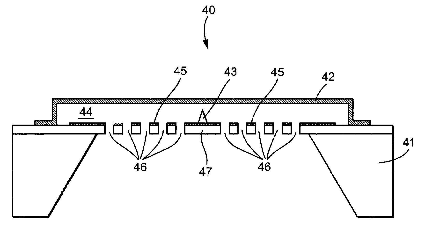
[0024]The present invention is an electron surface tunneling microphone with very high sensitivity in which a tunneling tip is integrated with a pressure sensitive membrane on a single support substrate.

[0025]A preferred embodiment of the electron surface tunneling microphone structure 40 of the present invention is shown in FIG. 5. As shown in FIG. 5, a tunneling tip 43 is placed on a single support substrate 41, where it is mounted on a rigid perforated suspension plate 47. As a result, the vibration sensitivity of the microphone is reduced to that of membrane 42. Suspended above plate 47, in a manner similar to other comparable microphone structures, is a thin flexible membrane 42. Also included on the suspension plate 47 are at least one, and preferably a plurality of control electrodes 45, which are used to move the conductive membrane 42 into close proximity with the tunneling tip 43. Movement of membrane 42 relative to tunneling tip 43 is achieved by applying an electrical po...


PUM


Abstract

An electronic surface tunneling acoustic detector or microphone with very high sensitivity is disclosed. A tunneling tip is mounted on a rigid perforated suspension plate, along with control electrodes, which are used to move a conductive membrane suspended above the suspension plate into closer or farther proximity with the tunneling tip. An electrical potential between the control electrodes and membrane, causing the membrane to bend towards the electrodes, and hence the tip, due to electrostatic attraction. As the membrane is pulled toward the tunneling tip, at some point a tunneling current begins to flow in the tunneling tip. The control voltage is subsequently adjusted to achieve a steady-state tunneling current in the tip. As the membrane responds to differential acoustic pressure variations, it moves and therefore upsets the adjusts the control voltage to return the membrane to the steady-state condition. As a result, the adjustment of the control voltage is a direct measure of any sound pressure incident upon the membrane.

Description

CROSS-REFERENCE TO RELATED APPLICATION[0001]This application claims the benefit of Provisional Application Ser. No. 60 / 568,691, filed May 7, 2004, the entire contents of which is hereby incorporated by reference in this application.FIELD OF THE INVENTION[0002]The present invention relates to acoustic detectors and microphones, and in particular, to a microphone with very high sensitivity, in which the detection mechanism is based on electron surface tunneling.BACKGROUND OF THE INVENTION[0003]Electron surface tunneling is a well known phenomenon. It is predicted by quantum mechanical theory, and is exploited in surface tunneling microscopes (STM) capable of distinguishing individual atoms on surfaces. The quantum theory of surface tunneling focuses on the possibility that an electron can jump from the electron cloud on the surface of one material to an electron cloud on the surface of another material. An important feature is that the two materials are physically separated by a “forb...

Claims


Application Information

Patent Timeline
Patent Type & Authority Patents(United States)
IPC IPC(8): H04R1/00H04R21/02H04R31/00
CPCH04R31/006H04R21/02H04R19/005H04R3/00H04R1/083
Inventor PEDERSEN, MICHAEL
Owner FOR NAT RES INITIATIVES
Why Eureka
Try Eureka