Mounting system for optical frequency reference cavities

a technology of optical frequency reference and mounting system, which is applied in the direction of optical resonator shape and construction, metal working apparatus, manufacturing tools, etc., can solve the problem of near-zero net change in the distance between the cavity mirrors, and achieve the effect of effectively preserving the upper/lower symmetry and facilitating the use of additional vibration isolation

Active Publication Date: 2007-04-26
UNIV OF COLORADO THE REGENTS OF
View PDF10 Cites 0 Cited by
  • Summary
  • Abstract
  • Description
  • Claims
  • Application Information

AI Technical Summary

Benefits of technology

[0019] In an alternative embodiment, holes can be drilled longitudinally from the end-faces of the extra-thick cylindrical cavity spacer, which also comprises the collar. These holes stop at a depth near the midplane, so that the supporting rods from below will provide the support again in the midplane, effectively preserving the upper / lower symmetry. For weight balance purposes, a corresponding set of dummy holes (normally unused) are prepared also in the top face, being rotated suitably around the longitudinal axis to provide an offset between the upper and lower hole systems.
[0020] Another useful variant is based on hanging the cavity from its symmetry plane by wires from above, rather than supporting it by rods from below. Again the weight-bearing points will be located essentially in the midplane of the cavity's vertical length. This variant facilitates use of additional vibration isolation within the vacuum housing, for example based on leaf springs, which would support the upper ends of the cavity support wires. Such leaf springs, as loaded by the cavity mass, will function as an in situ low pass filter for mechanical vibrations. Therefore, considering the low a priori vibration sensitivity achievable with the vertically-mounted cavity concept, it may be possible in some cases to dispense with any vibration reduction efforts external to the cavity's vacuum enclosure.

Problems solved by technology

By using vertical symmetry relative to the horizontal midplane of an optical cavity, even large vibration induced distortions of the cavity's spacer result in near-zero net change in the distance between the cavity mirrors.

Method used


Image

  • Mounting system for optical frequency reference cavities
  • Mounting system for optical frequency reference cavities
  • Mounting system for optical frequency reference cavities

Examples


Embodiment Construction

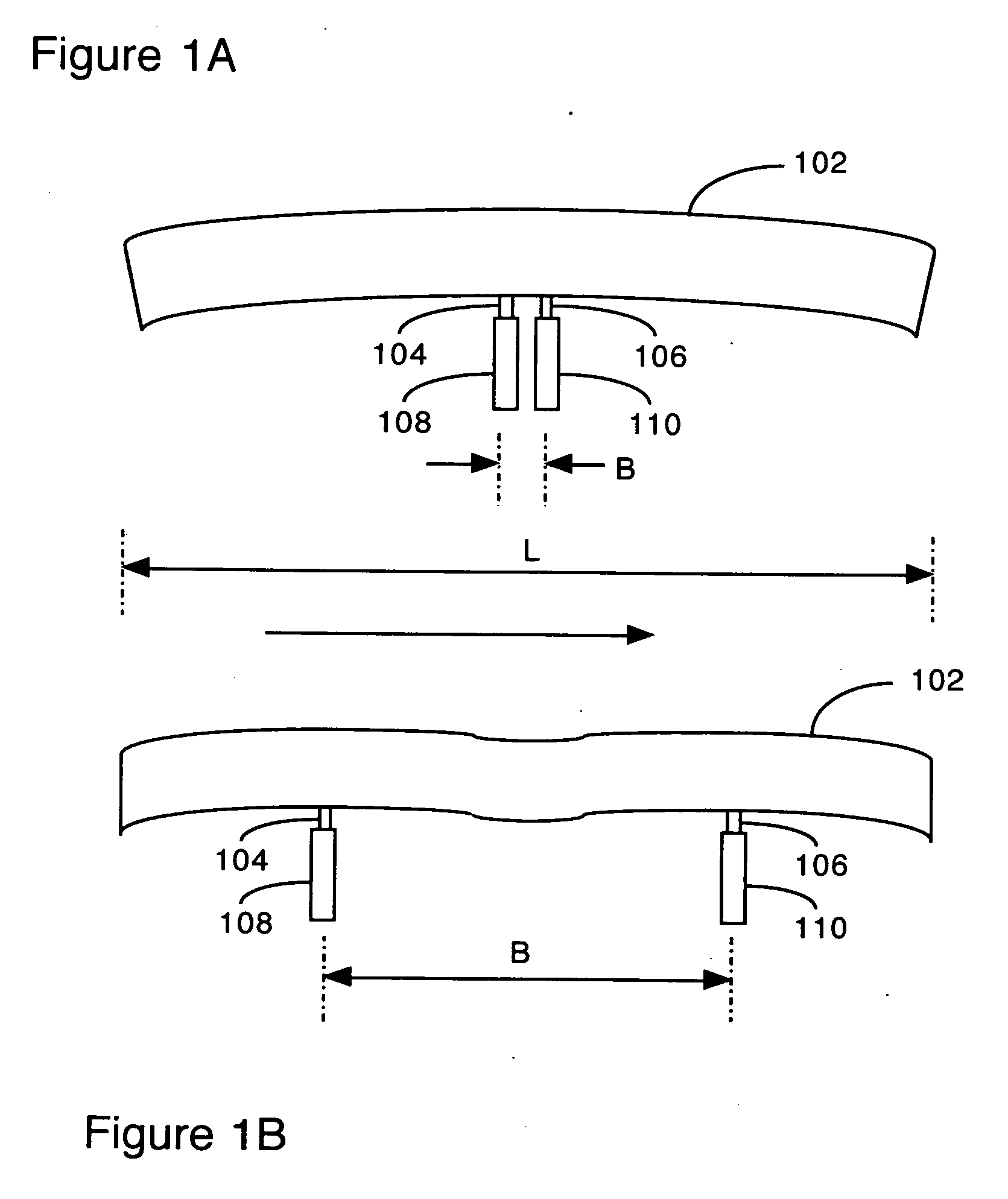
[0026]FIGS. 1A and 1B (Prior Art) are simplified side-section diagrams illustrating the conventional horizontal mounting of optical frequency reference cavities 102. Note that the diagrams are not to scale, but are exaggerated for clarity. Both show gravity induced sag of the structure perpendicular to the cavity axis. In the top diagram of FIG. 1A, cavity spacer 102 is supported in two places 104, 106 by, for example, V-blocks 108, 110 which are nearly adjacent (B=0.11L). Such a narrow spacing is chosen to reduce coupling of temperature induced length changes. Unfortunately, this orientation appears to be especially sensitive to vertical vibrations. In addition, the mirror faces on the ends are not parallel because of the bowing of spacer 102.

[0027] The lower diagram of FIG. 1 B shows cavity spacer 102 supported in two places 104,106 by, for example, V-blocks 108, 110. V-blocks 108,110 are separated at a special value (B=0.577L), forming what is known as an “Airy” suspension confi...


PUM

PropertyMeasurementUnit
diameteraaaaaaaaaa
diameteraaaaaaaaaa
cavity lengthaaaaaaaaaa

Abstract

A technique for reducing the vibration sensitivity of laser-stabilizing optical reference cavities is based upon an improved design and mounting method for the cavity, wherein the cavity is mounted vertically. It is suspended at one plane, around the spacer cylinder, equidistant from the mirror ends of the cavity. The suspension element is a collar of an extremely low thermal expansion coefficient material, which surrounds the spacer cylinder and contacts it uniformly. Once the collar has been properly located, it is cemented in place so that the spacer cylinder is uniformly supported and does not have to be squeezed at all. The collar also includes a number of cavities partially bored into its lower flat surface, around the axial bore. These cavities are support points, into which mounting base pins will be inserted. Hence the collar is supported at a minimum of three points.

Description

PRIORITY [0001] This application claims the benefit of U.S. Provisional Patent Application Nos. 60 / 711,955, filed Aug. 25, 2005, and 60 / 71 3,834, filed Sep. 2, 2005 and incorporates them herein by reference.GOVERNMENT SUPPORT: [0002] The present invention was made with government support as follows. NSF, Grant #s PHY00-96822, “the JLA Research Program in Atomic, Molecular, and Optical Physics”, C. E. Wieman and W. C. Lineberger Office of Naval Research, N0001 4-02-1-0714, “Optical Atomic Clocks”, Jun Ye NASA NAGS-10368, “Optical Local Oscillator with 1×10⁻¹⁵ Frequency Stability”, J. Hall and J. Ye, ended Feb. 14, 2004BACKGROUND OF THE INVENTION [0003] 1. Field of the Invention [0004] The present invention relates to techniques for mounting optical frequency reference cavities in such a manner as to reduce the effects of mechanical vibration. [0005] 2. Problems in the Art [0006] A common method of achieving optical frequency stability in a laser is to use a laser whose output frequen...

Claims


Application Information

Patent Timeline
Patent Type & Authority Applications(United States)
IPC IPC(8): H01S3/00
CPCH01S3/02Y10T29/49865Y10T29/51H01S3/1392
Inventor NOTCUTT, MARKHALL, JOHN L.MA, LONG-SHENG
Owner UNIV OF COLORADO THE REGENTS OF
Why Eureka
Try Eureka