Phase shifting device

a phase shift and phase shifting technology, applied in pulse generators, pulse manipulation, pulse techniques, etc., can solve the problems of difficult output, inability to make the frequency of output signals and input signals different from each other, and errors in 90-degree phase shift and amplitud

Inactive Publication Date: 2007-10-16
PANASONIC CORP
View PDF13 Cites 20 Cited by
  • Summary
  • Abstract
  • Description
  • Claims
  • Application Information

AI Technical Summary

Benefits of technology

[0015]Another object of the present invention is to provide a phase shifting device capable of making the frequency of output signals N times the frequency of an input signal.
[0046]According to the present invention, in an orthogonal modulator and a demodulator for orthogonally modulated signals, for example, orthogonal carrier signals can be outputted so as to have a 90-degree phase shift and equal amplitude which are of proper orthogonal signals, achieving a highly accurate orthogonal phase modulation / demodulation scheme.

Problems solved by technology

In the aforementioned conventional art 90-degree phase shifter, due to variation in value between elements or the influence of parasitic components in the integrated circuit, errors may occur in 90-degree phase shift and amplitude.
With the configuration of the conventional art shown in FIG. 10, however, it is not possible to make the frequency of output signals and the frequency of an input signal different from each other.
Since there is a limit to the amount of phase shift rotation that can be created with a variable phase shifter having a simple configuration, such as a CR variable phase shifter, it is difficult to output, with a simple configuration, signals having a large amount of phase shift rotation.
Thus, if a variable resistor or a variable capacitor is connected in series between the input and output terminals of the variable phase shifter 111, the resistance value of the variable resistor or the capacitance value of the variable capacitor changes in accordance with the change in potential, causing unstable operation of the variable phase shifter.

Method used


Image

  • Phase shifting device
  • Phase shifting device
  • Phase shifting device

Examples


first embodiment

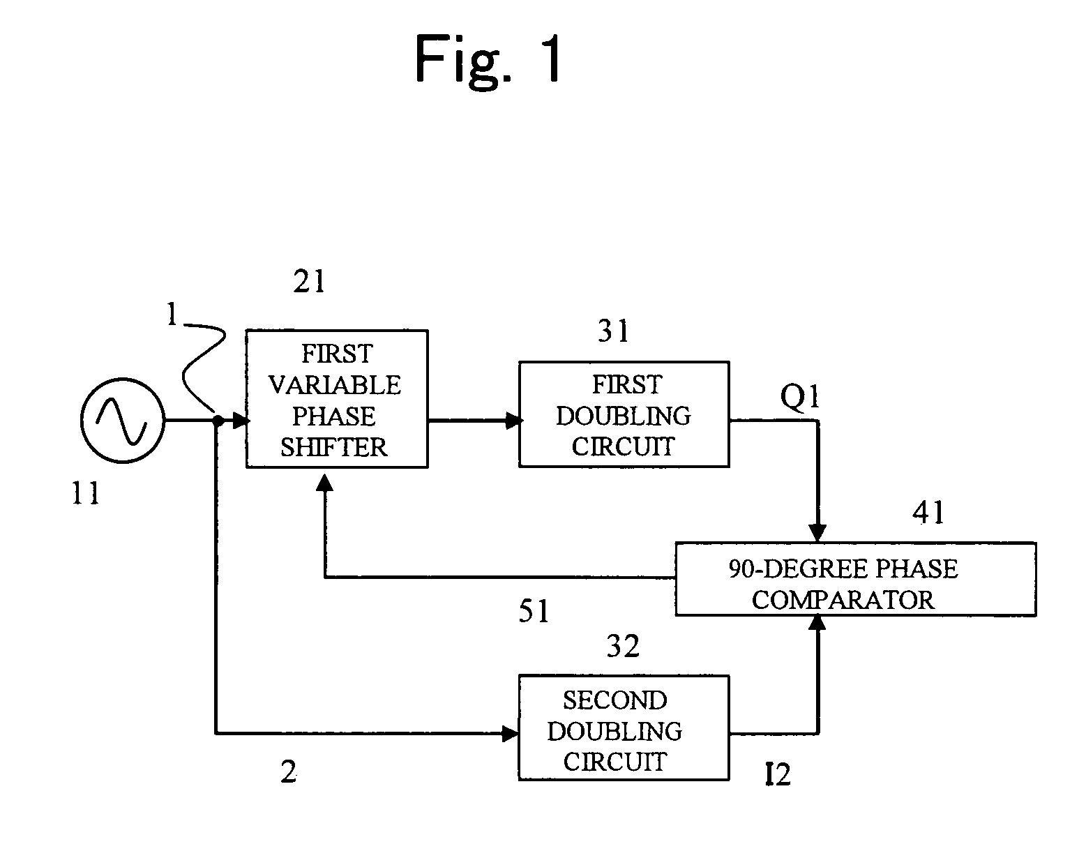
[0065]A 90-degree phase shifting device according to a first embodiment of the present invention is shown in FIG. 1. The 90-degree phase shifting device has a signal source 11; a first variable phase shifter 21 capable of changing the amount of phase shift rotation by a first phase shift control signal 51; a first doubling circuit 31; a second doubling circuit 32; and a 90-degree phase comparator 41. Here, an output from the signal source 11 is split into two parts which serve as a first input signal 1 and a second input signal 2, respectively.

[0066]When the first input signal 1 and the second input signal 2 are written as V1 and V2, respectively, V1 and V2 are defined as follows:

V1=V2=A*exp(jωt),

where A is the amplitude and ω is the angular frequency.

[0067]When the output from the first variable phase shifter 21 is written as V21, V21 is defined as follows:

V21=B*exp(jωt+θ),

where B is the amplitude and θ is the amount of phase shift rotation of the first variable phase shifter 21. W...

second embodiment

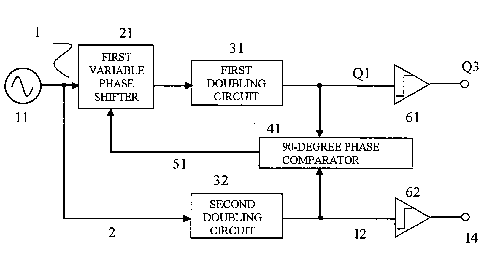
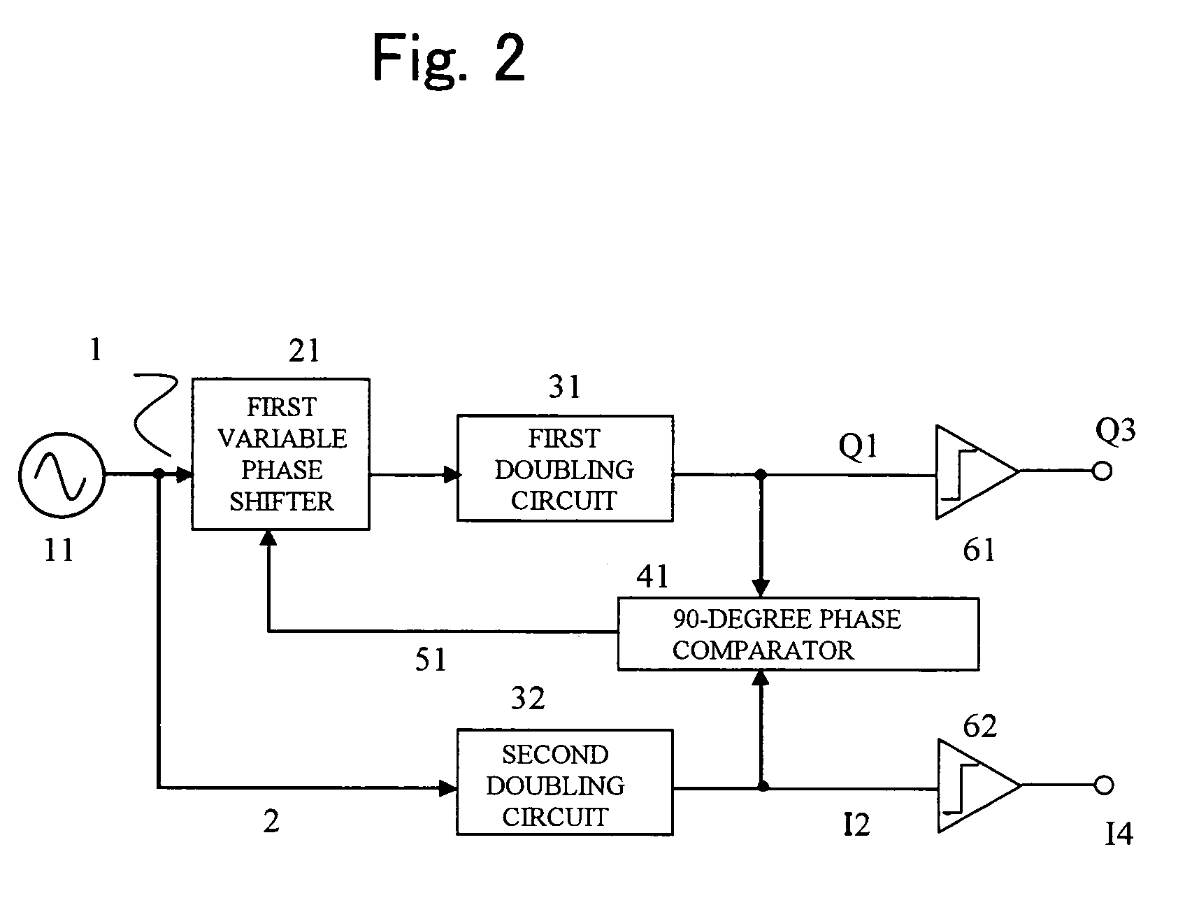
[0075]In the above-described 90-degree phase shifting device of FIG. 1 according to the first embodiment, although a phase shift of exactly 90 degrees can be achieved, the amplitudes are not always equal. While the first input signal 1 passes through the first variable phase shifter 21, the second input signal 2 does not pass through any variable phase shifter; therefore, a large amplitude error occurs between the first output signal Q1 and the second output signal I2.

[0076]A second embodiment of the present invention is shown in FIG. 2. The second embodiment provides a 90-degree phase shifting device with which not only an exact 90-degree phase shift can be achieved as in the first embodiment but also equal amplitude output signals can be obtained.

[0077]In the 90-degree phase shifting device, an input of a first gain limiting circuit 61 is connected to a first output signal Q1, and an output from the first gain limiting circuit 61 serves as a third output signal Q3. In addition, an...

third embodiment

[0079]A third embodiment of the present invention is shown in FIG. 3. The third embodiment provides a 90-degree phase shifting device with which not only an exact 90-degree phase shift can be achieved as in the first embodiment but also equal amplitude output signals can be obtained.

[0080]In the 90-degree phase shifting device, an input of a variable-gain amplifier 71 is connected to a first output signal Q1, and an output from the variable-gain amplifier 71 serves as a third output signal Q3. In addition, a second output signal I2 and the third output signal Q3 are connected to inputs of a level comparator 81. An output from the level comparator 81 is fed back, as a gain control signal 91, to the variable-gain amplifier 71.

[0081]By this, the gain of the variable-gain amplifier 71 is controlled such that the amplitudes of the second output signal I2 and the third output signal Q3 are equal. Accordingly, the third output signal Q3 and the second output signal I2 have equal amplitude....


PUM


Abstract

A phase shifting device includes a signal source; a variable phase shifter; first and second doubling circuits; and a 90-degree phase comparator. An output from the signal source is connected to an input of the variable phase shifter and to an input of the second doubling circuit, an output from the variable phase shifter is connected to an input of the first doubling circuit, an output from the first doubling circuit serves as a first output signal, and an output from the second doubling circuit serves as a second output signal. The first output signal and the second output signal are inputted to the 90-degree phase comparator. The amount of phase shift rotation of the variable phase shifter is changed by a phase shift control signal outputted from the 90-degree phase comparator. By this, an exact 90-degree phase shift is obtained.

Description

BACKGROUND OF THE INVENTION[0001]1. Field of the Invention[0002]The present invention relates to a phase shifting device for use in a wireless communication apparatus including a mobile communication terminal.[0003]2. Description of the Background Art[0004]In a 90-degree phase shifter used in a modulator-demodulator for orthogonal modulation signals, in order to obtain proper orthogonal signals, a 90-degree phase shift and equal amplitude need to be achieved with a high degree of accuracy.[0005]As a 90-degree phase shifter having the simplest configuration, there is shown in FIG. 9 a phase shifter of a first conventional art. In the 90-degree phase shifter, the phase of an input signal is subjected to a +45-degree phase shift rotation using a circuit having a high-pass filter configuration composed of a resistor R11 and a capacitor C11. In addition, the phase of an input signal is subjected to a −45-degree phase shift rotation using a circuit having a low-pas filter configuration co...

Claims


Application Information

Patent Timeline
Patent Type & Authority Patents(United States)
IPC IPC(8): H03H11/16H03H7/20H03H7/21H03H11/22
CPCH03H7/20H03L7/0812H03H11/20H03K2005/00286
Inventor TANAKA, TAKATOSHITANABE, MITSURUKATAOKA, SHIGERU
Owner PANASONIC CORP
Why Eureka
Try Eureka