Inmate transport restraint

a technology for restraints and inmates, applied in the field of human restraint devices, can solve the problems of inability to use restraints more than, inability to meet the needs of inmates, so as to reduce the physical fatigue and injury of restraint individuals, and achieve the effect of effective and secur

Active Publication Date: 2007-10-23
SISCO VERNON G
View PDF58 Cites 33 Cited by
  • Summary
  • Abstract
  • Description
  • Claims
  • Application Information

AI Technical Summary

Benefits of technology

[0014]Accordingly, it is an object of this invention to provide an effective and secure means for the transport of inmates.
[0015]It is a further object of this invention to reduce the physical fatigue and injury of restrained individuals during transport.

Problems solved by technology

Typically, these devices are constructed so that locking mechanism only allows the strap to move in one direction such that the loops can be made smaller but cannot be made larger.
This type of restraint is not suitable for the routine transport of inmates.
These restraints are typically not suitable to be used more than once.
Although these devices each have a loop which can be tightened, they are designed to hold the snout, or some other body part, of an animal and are not suitable for use on humans.

Method used


Image

  • Inmate transport restraint
  • Inmate transport restraint
  • Inmate transport restraint

Examples


Embodiment Construction

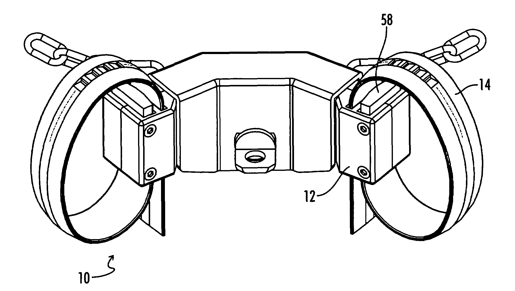
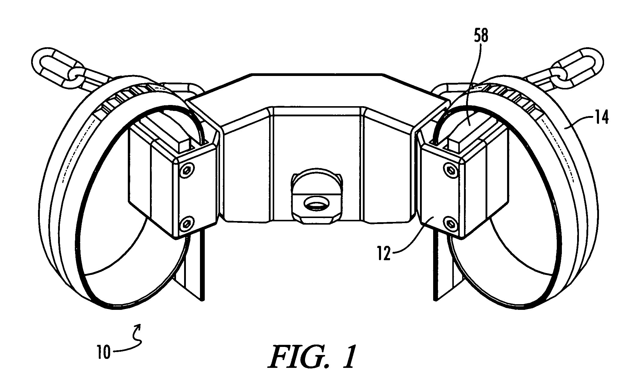
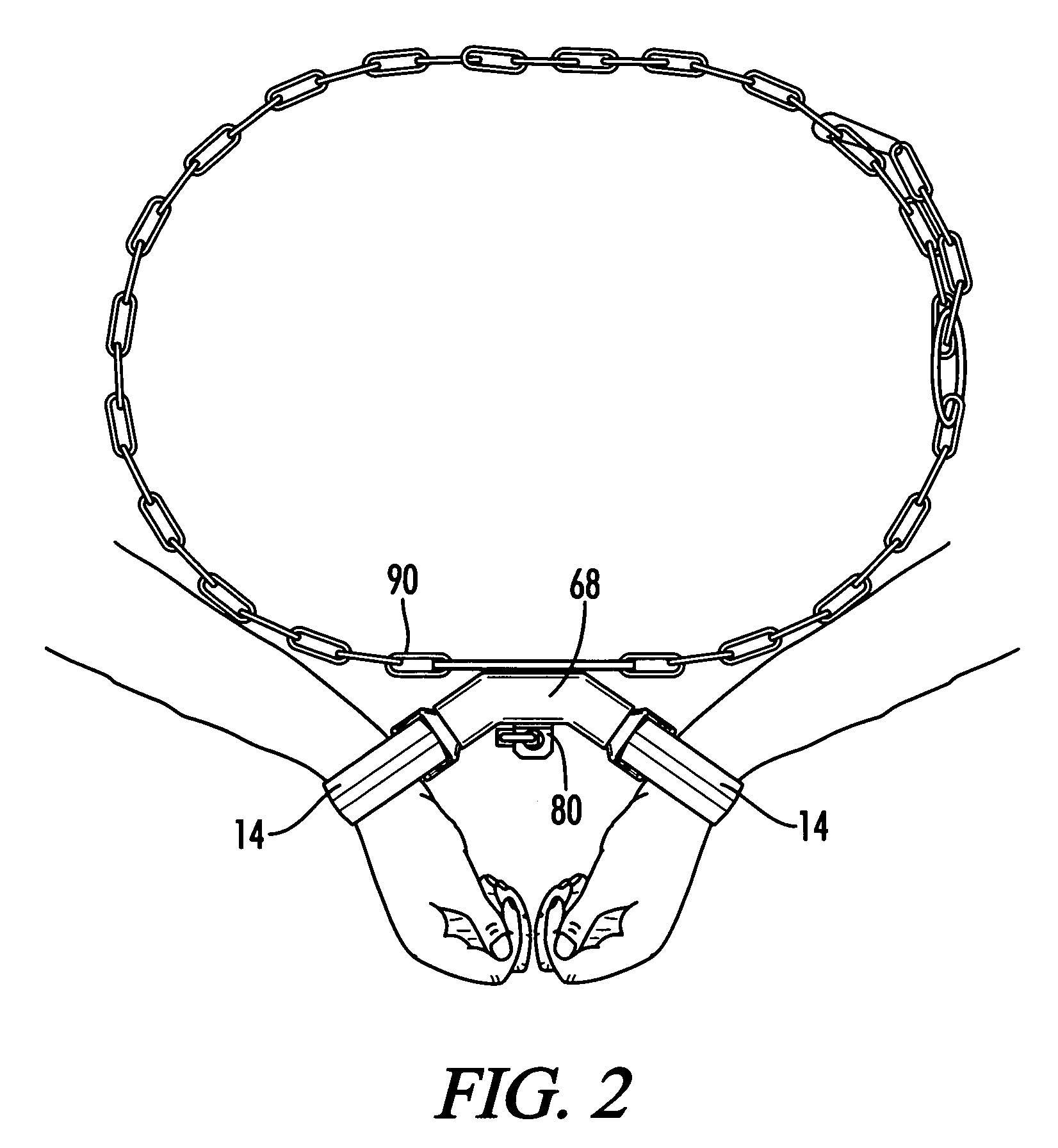
[0033]Referring now to the drawings, wherein like reference numerals refer to like parts throughout, the handcuff of the present invention is referred to as 10. As shown in FIGS. 1 and 9, the handcuff 10 comprises a housing 12 and a strap 14. The strap 14 passes through the housing 12 and forms a loop through which a person's hand or foot is passed so that the loop can be tightened around the wrist or ankle to restrain the person. The strap 14 may also be wrapped around a person's foot or hand and then secured with the housing 12. It is contemplated that the present invention would be useful in restraining inmates as well as restraining persons in medical, psychiatric or other settings where restraint is necessary.

[0034]Referring now to FIG. 9, the housing 12 is comprised of a front plate 24 and a rear plate 26. In the preferred embodiment, the housing 12 is constructed from impact plastic or 7075 aluminum. The tension spring 36, lift cam 38 and pin 44 fit inside the housing 12. In ...


PUM


Abstract

An inmate transport restraint which comprises a handcuff having two loops formed from two straps, each strap separately inserted into a housing, wherein each housing has a first channel and a second channel, with the strap passing through each channel, the second channel adapted for releasably retaining a free end of the strap and the first channel retaining a stop end of the strap in a semi-permanent manner, the housing further containing a key-operated lift cam that cooperates with a tension spring to releasably retain the strap within the housing. The restraint further comprises a handcuff cover which fits over a portion of the handcuff to limit access and movement of the hands and wrists. The cover cooperates with a link pin, attached to a belly chain, to secure an inmate for transport.

Description

CROSS-REFERENCES TO RELATED APPLICATIONS[0001]This application is a Continuation-In-Part application which claims benefit of co-pending U.S. patent application Ser. No. 11 / 031,575 filed Jan. 6, 2005, entitled “Restraint Device” which is hereby incorporated by reference and which claims the benefit of U.S. Provisional Patent Application Ser. No. 60 / 623,319 filed Oct. 29, 2004 and entitled “Restraint Device” which is also incorporated by reference.STATEMENT REGARDINGFEDERALLY SPONSORED RESEARCH OR DEVELOPMENT[0002]Not ApplicableREFERENCE TO SEQUENCE LISTING OR COMPUTER PROGRAM LISTING APPENDIX[0003]Not ApplicableBACKGROUND OF THE INVENTION[0004]The present invention relates generally to human restraint devices. More particularly, this invention pertains to a humane restraint device and a system and method of restraint for the transport of inmates consisting of a handcuff, handcuff cover and a belly chain link pin, which cooperate in a unique manner with each other.[0005]The restraint ...

Claims


Application Information

Patent Timeline
Patent Type & Authority Patents(United States)
IPC IPC(8): E05B75/00
CPCE05B75/00Y10T24/1498Y10T70/404
Inventor SISCO, VERNON G.
Owner SISCO VERNON G
Why Eureka
Try Eureka