
Control system for an industrial automation facility and method for programming and operating such a control system

a control system and industrial automation technology, applied in the direction of program control, electric programme control, instruments, etc., can solve the problem of not being able to ensure the consistency of the version history

Active Publication Date: 2021-01-26
WEIDMULLER INTERFACE GMBH & CO KG
View PDF7 Cites 0 Cited by
  • Summary
  • Abstract
  • Description
  • Claims
  • Application Information

AI Technical Summary

Benefits of technology

[0013]The assignment of binary program and program understandable at any time prevents unwanted splitting of a program into different development branches as a result of older development states of the program being unintentionally further developed where more recent development states already exist. In the further embodiment, the complete version history is available for every web browser, irrespective of the accessing computer.
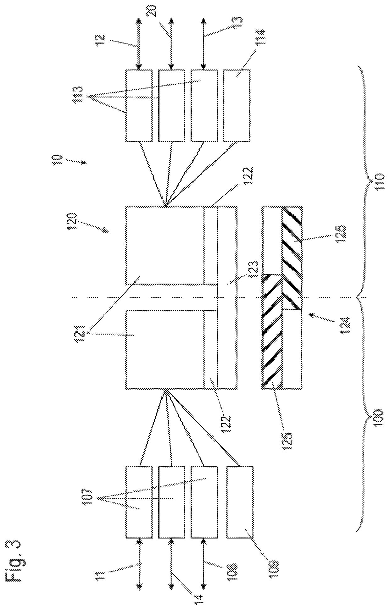
[0018]In one embodiment of the control system, an effective and secure separation between the real-time system and the non-real time system can be implemented by different processors being assigned to the real-time system and the non-real time system. An advantageous alternative includes a processor for the control system having at least two cores, with at least one core being assigned to the real-time system and at least one core to the non-real time system.

Problems solved by technology

Such a development environment has the disadvantage that a computer equipped with this development environment, e. g. a PC, which is coupled to the control system, must be available for programming the control system.
In addition, if several developers access the control system from different PCs with such a development environment, a consistent version history is no longer ensured.

Method used


Image

  • Control system for an industrial automation facility and method for programming and operating such a control system
  • Control system for an industrial automation facility and method for programming and operating such a control system
  • Control system for an industrial automation facility and method for programming and operating such a control system

Examples


Embodiment Construction

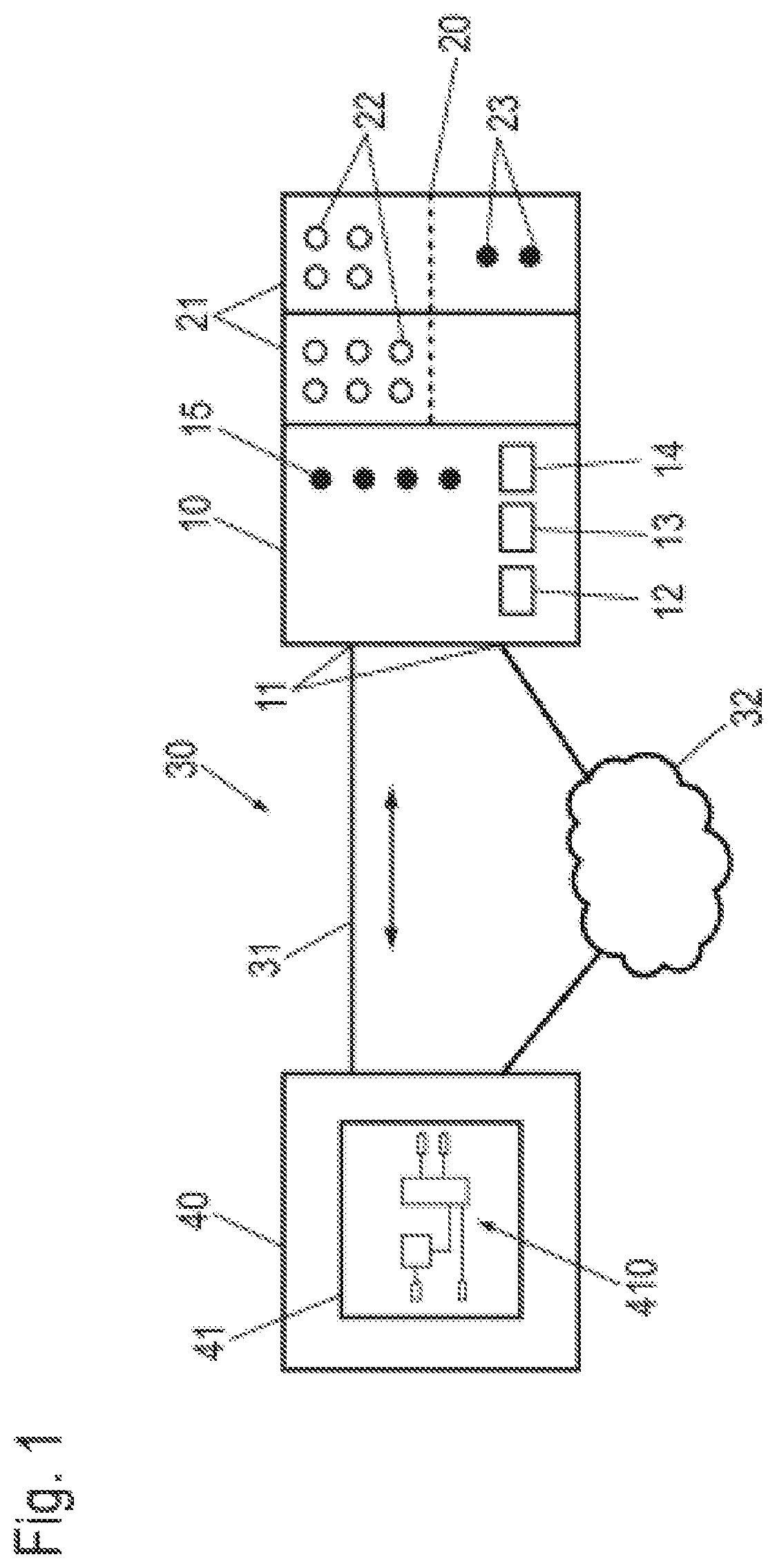
[0026]FIG. 1 shows an exemplary industrial automation facility with a control system 10 in the form of a block diagram. As an example, two I / O modules 21 having inputs 22 and outputs 23 coupled to components and / or sensors of the industrial facility are connected to the control system 10 via a bus system 20, which can be a field bus system or a proprietary bus. The control system 10 has at least one network connection 11 as well as other connections, e. g. a field bus connection 12, another field bus connection 13, and a USB (Universal Serial Bus) connection 14 as well as control displays 15.

[0027]For programming, the control system 10 is connected to a computer 40 via the network connection 11 and a network 30. The computer 40 is only used for programming the control system 10. For control operation, the control system 10 is independent of the computer 40 and can be operated autonomously without the computer.

[0028]As an example, two connections between the control system 10 and the...


PUM


Abstract

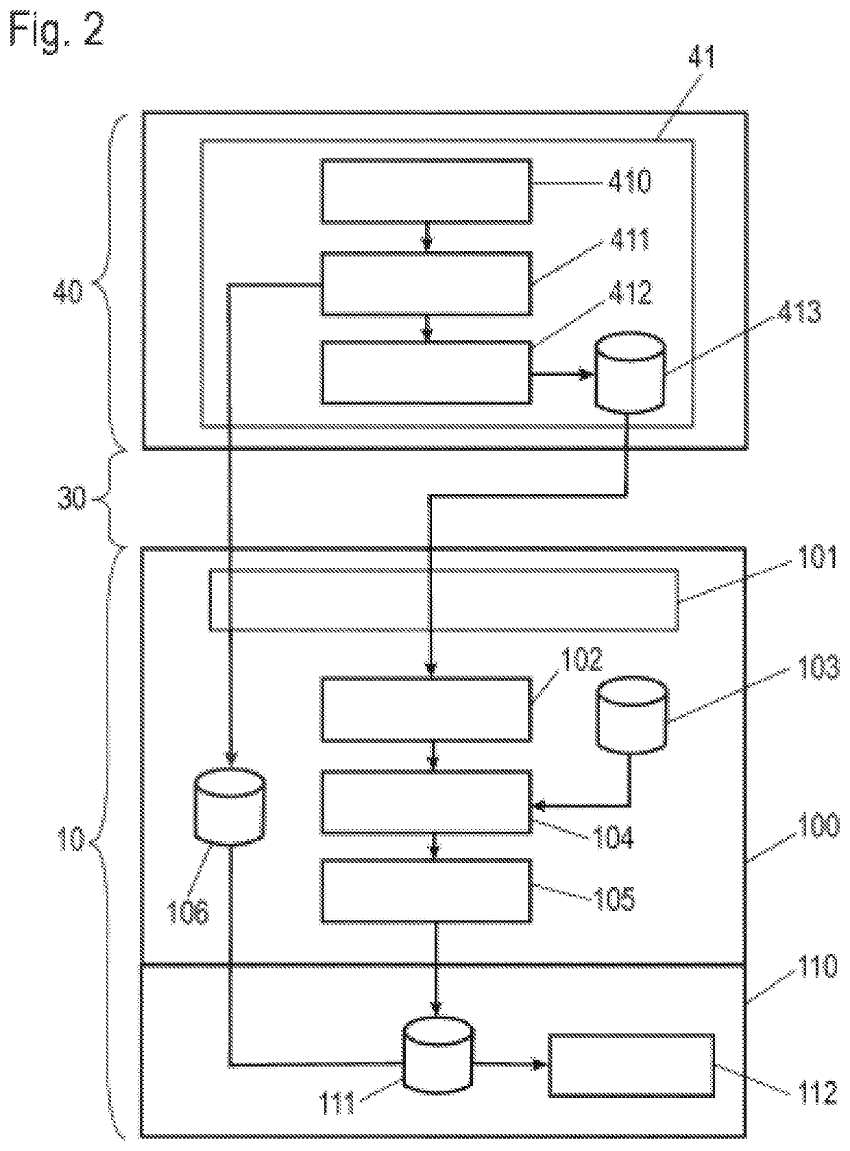
A control system for an industrial automation facility and a method for programming and operating the control system use a program for the control system which is developed with a development tool. Data from a web server built into the control system is transmitted to a computer which is connected to the control system via a network. The data includes a web-based development environment. A representation of the development environment in a web browser is embodied on the computer. A program for the control system is developed or processed by a user. The program developed and / or processed by the user is converted into a high-level language program by a conversion module embodied in the web browser. The high-level language program is transmitted to the control system and converted into a binary program inside the control system. The binary program is implemented by the control system.

Description

CROSS-REFERENCE TO RELATED APPLICATIONS[0001]This application is a § 371 National Stage Entry of International Patent Application No. PCT / EP2017 / 079932 filed Nov. 21, 2017. Application No. PCT / EP2017 / 079932 claims priority of DE102016122324.7 filed Nov. 21, 2016. The entire content of these applications are incorporated herein by reference.BACKGROUND OF THE INVENTION[0002]The invention relates to a method for programming and operating a control system of an industrial automation facility, which a program for the control system is developed with a development tool.[0003]The invention further relates to a control system suitable for performing the method.[0004]Industrial automation facilities provide process control and monitoring of automated industrial facilities. Typically, they have an industrial automation control system, also referred to as a programmable logic controller (PLC) and hereinafter referred to in short as a control system. The control system is directly coupled to fi...

Claims


Application Information

Patent Timeline
Patent Type & Authority Patents(United States)
IPC IPC(8): G05B19/04G06F8/34G05B19/042G06F9/451G05B19/05G06F8/30
CPCG05B19/0426G05B19/05G06F8/315G06F8/34G06F9/451
Inventor KRONER, MICHAELBIRNBAUM, IMMOBRINKMANN, SEBASTIANBROCKMEYER, MICHAELHARRING, FELIXHERBRECHTSMEIER, STEFANPETERS, CHRISTIAN
Owner WEIDMULLER INTERFACE GMBH & CO KG
Learn More