Self-aligning stuffing box

a self-aligning and stuffing box technology, applied in the direction of fluid removal, mechanical equipment, construction, etc., can solve the problems of shortened and less effective pumping stroke, excessive wear of both the packing and the rod, and lateral loading of the stuffing box, so as to prevent lateral loading and reduce the height of the upper tubular housing

Inactive Publication Date: 2007-10-23
MSI MACHINEERING SOLUTIONS INC
View PDF12 Cites 15 Cited by
  • Summary
  • Abstract
  • Description
  • Claims
  • Application Information

AI Technical Summary

Benefits of technology

[0008]A relatively low profile self-aligning stuffing box has a spherical joint formed between and upper tubular housing and a lower tubular housing for permitting misalignment of the upper housing relative to the lower housing for passage of a rod therethrough preventing lateral loading of the stuffing box. A first seal is housed in a bore in the upper tubular housing in a downwardly depending central cylindrical portion of the lower end of the upper tubular housing formed within a concave spherical face which forms an upper surface of the spherical joint. The downwardly depending central portion of the upper housing protrudes into a recess formed in the upper end of the lower tubular housing at a center of a convex spherical surface forming a lower surface of the spherical joint. Positioning of the first seal, at or below the spherical joint, permits the height of the upper tubular housing to be reduced. A second seal is positioned above the first seal in the bore of the upper housing.

Problems solved by technology

If the rod is not axially aligned within the bore of the stuffing box, excessive wear of both the packing and the rod can occur.
In extreme cases of wear the rod can fail and drop into the wellbore, leaving the wellbore open to the surface.
Misalignment may occur for many reasons such as resulting from settling of the pumpjack or rotary drive on a base or due to misalignment of the wellhead or stuffing box during assembly thereof.
Height of the wellhead may become problematic if insufficient bridle clearance is available between a pumpjack bridle and the wellhead, resulting in a shortened and less effective pumping stroke.
As is the case in U.S. Pat. No. 6,412,783 to Finnestad, many valves are positioned below the packing elements in the stuffing box and therefore, in order to replace or service the valves, the wellhead and stuffing box must be disassembled which is costly and time-consuming.

Method used


Image

  • Self-aligning stuffing box
  • Self-aligning stuffing box
  • Self-aligning stuffing box

Examples


Embodiment Construction

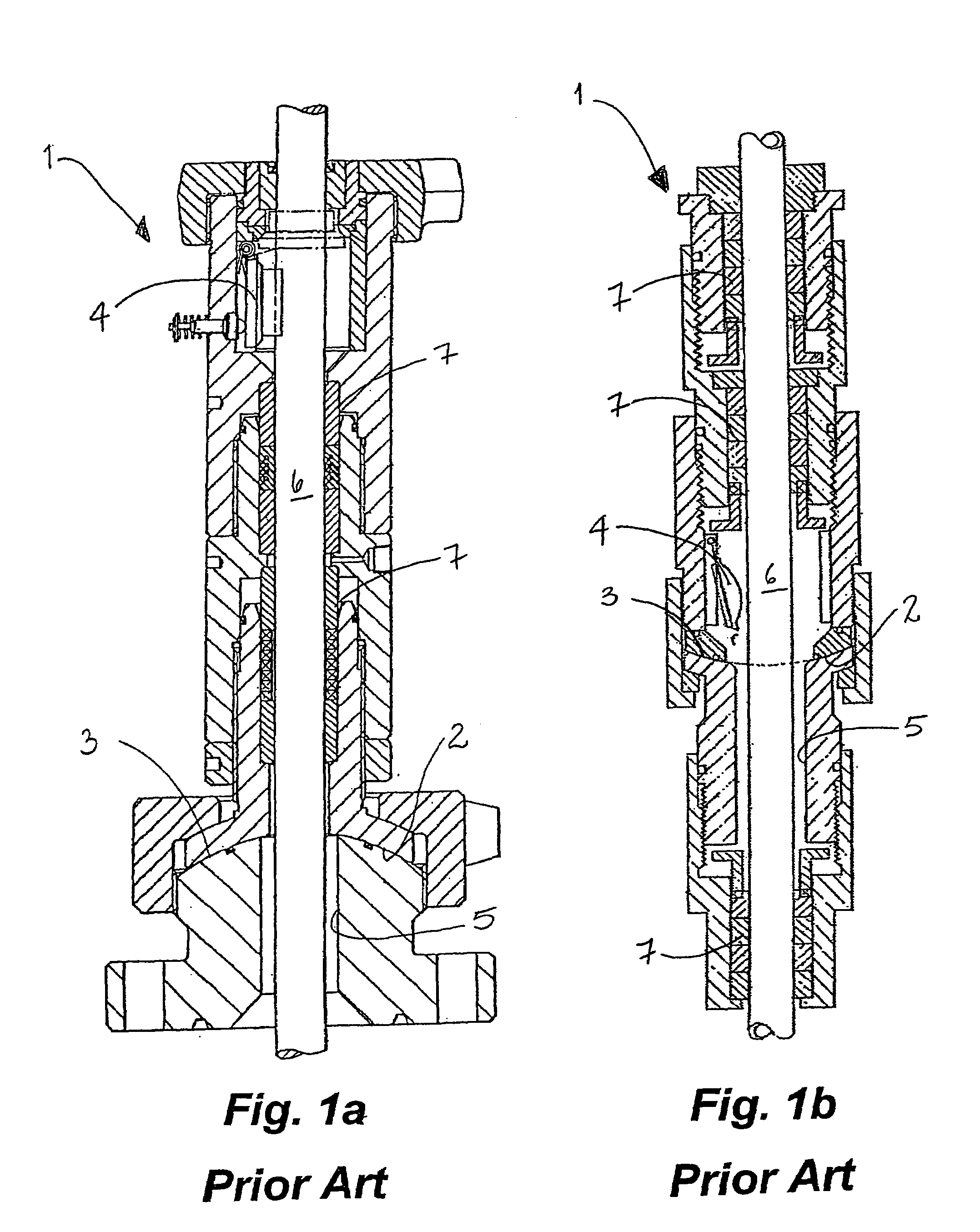
[0024]Having reference to FIGS. 1a and 1b, prior art self-aligning stuffing boxes 1 typically have a relatively high profile due to positioning of the components housed within the stuffing boxes 1 significantly above the alignment surfaces 2,3. Further, valve means 4 pivotally mounted within a bore 5 of the stuffing box 1 for sealing the bore 5 in the absence of a rod 6 are conventionally mounted either above or below sealing means 7 housed within the bore 5. Access to the valve means 4 for servicing or replacement is typically through disassembly of at least a portion of the stuffing box 1.

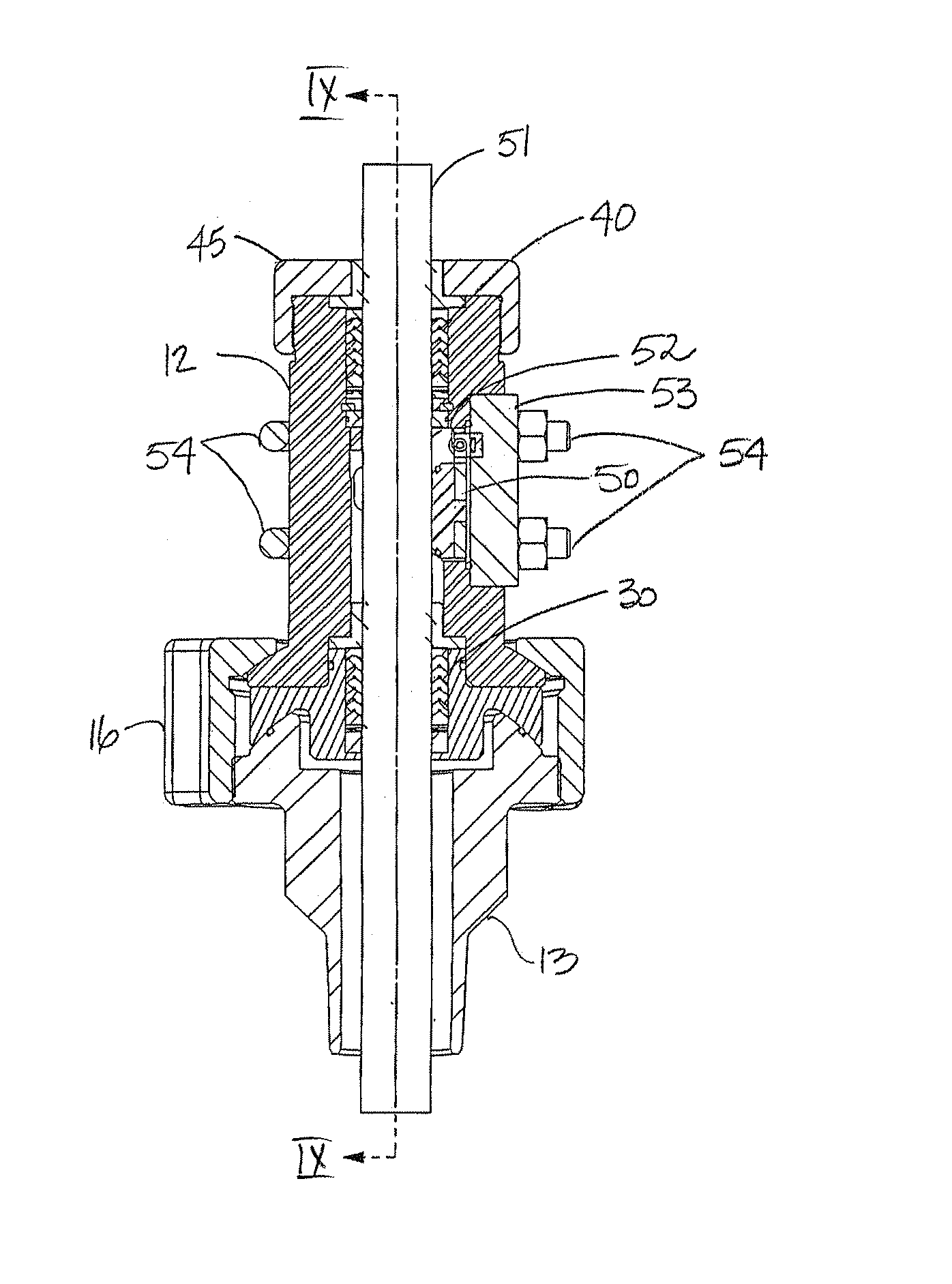
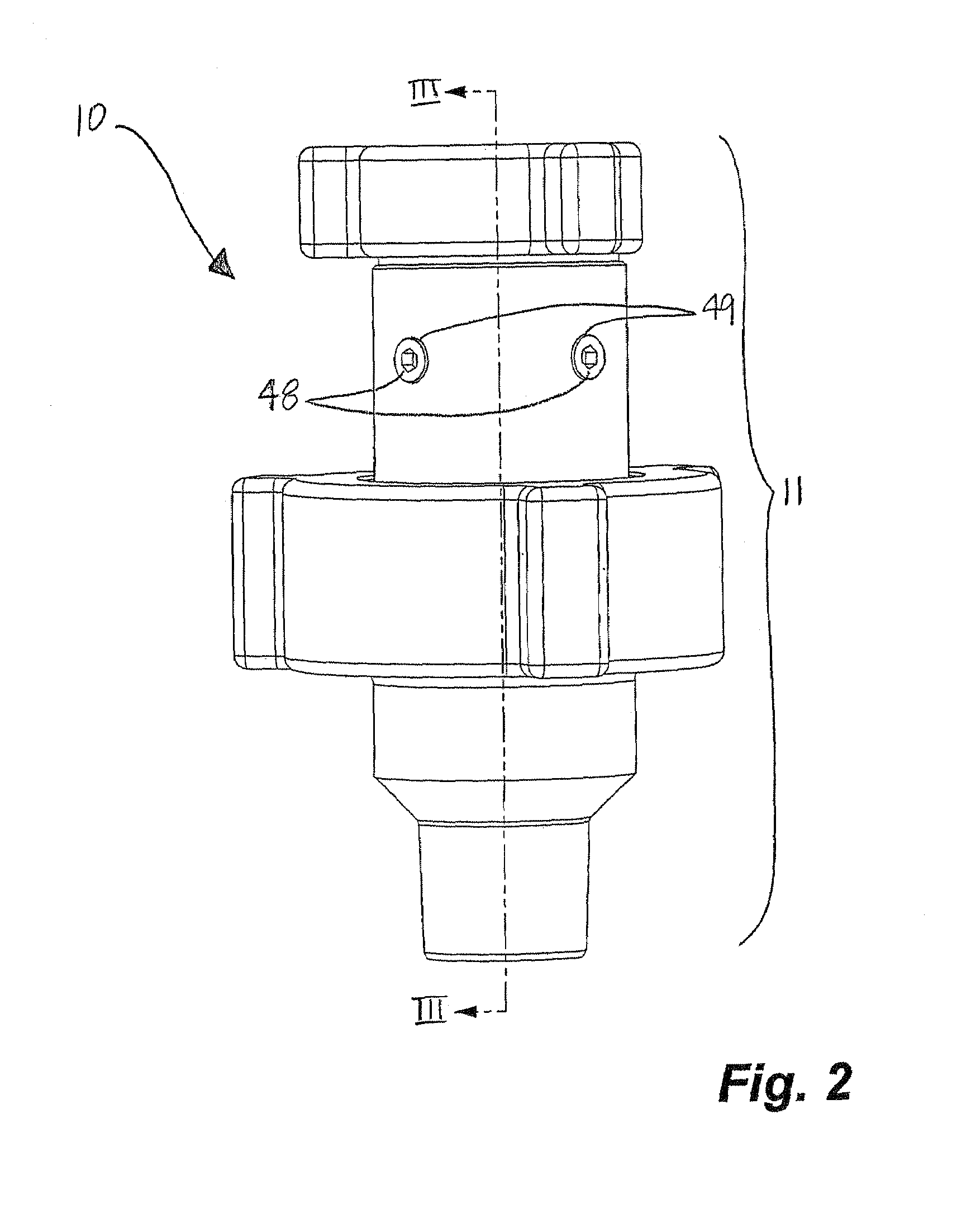
[0025]As shown in FIGS. 2-4, a low profile stuffing box 10 comprises a housing 11 for connection to a wellhead (not shown). The housing 11 comprises and upper tubular housing 12 and a lower tubular housing 13, each of the upper and lower tubular housings 12, 13 having bores 14, 15 formed therein. A lower end 17 of the upper tubular housing 12 is coupled to an upper end 21 of the lower tubular hou...


PUM


Abstract

A self-aligning stuffing box having a spherical joint between the upper and lower portions of the housing permits universal movement of the upper portion relative to the lower portion to permit a rod to pass through the bore if the axis of the rod is misaligned relative to the axis of the bore in each of the upper and lower housing portions. An energized seal in the upper housing resides at or below the spherical joint due to a downwardly depending central portion of the upper housing which extends into a recess formed in the lower housing permitting the height of the stuffing box to be relatively short. A second seal is positioned above the first seal and may be spaced sufficiently above the first seal to permit a flapper valve to be installed between the seals. The flapper valve is mounted through a port in the upper housing which is accessible without disassembly of the stuffing box, the seals or the wellhead.

Description

FIELD OF THE INVENTION[0001]Embodiments of the invention relate to wellhead assemblies and particularly to self-aligning stuffing boxes for a wellhead.BACKGROUND OF THE INVENTION[0002]Conventionally beam pumps, or rod pumps, commonly known as pumpjacks, reciprocate a polished rod extending axially through a stuffing box which contains packing to seal against the polished rod. Further, rotary pumps rotate a rod within the stuffing box. In each case, the seal prevents wellbore fluids from leaking from the wellhead during movement of the rod. If the rod is not axially aligned within the bore of the stuffing box, excessive wear of both the packing and the rod can occur. In extreme cases of wear the rod can fail and drop into the wellbore, leaving the wellbore open to the surface. Misalignment may occur for many reasons such as resulting from settling of the pumpjack or rotary drive on a base or due to misalignment of the wellhead or stuffing box during assembly thereof.[0003]Conventiona...

Claims


Application Information

Patent Timeline
Patent Type & Authority Patents(United States)
IPC IPC(8): E21B19/00
CPCE21B33/08F16J15/187E21B34/02E21B2034/005E21B2200/05
Inventor TESSIER, LYNN P.DOYLE, JOHN P.WEBER, JAMES L.
Owner MSI MACHINEERING SOLUTIONS INC
Why Eureka
Try Eureka