Lubrication pump

a lubrication pump and piston technology, applied in the field of lubrication systems, can solve the problems of increasing the time and cost of manufacturing the lubrication pump, reducing increasing the wear between the pistons, so as to reduce the tolerance and the life of the lubrication pump, prevent the piston from lateral loading, and increase the wear.

Active Publication Date: 2020-02-04
FD JOHNSON
View PDF4 Cites 0 Cited by
  • Summary
  • Abstract
  • Description
  • Claims
  • Application Information

AI Technical Summary

Benefits of technology

[0004]While known lubrication pumps of the type described above may have one or more pistons actuated by a camshaft within a housing bore to provide lubricant fluid flow, these pistons typically require accurate alignment with the camshaft and the housing bore to prevent lateral loading of the piston against the housing surface defining the bore. This lateral loading may increase wear between the piston and the housing surface defining the bore, thereby reducing tolerances and the life of the lubrication pump. Such accurate alignment and tighter tolerances for preventing such lateral loading also may increase the time and cost to manufacture the lubrication pump. In addition, known lubrication pumps are not easily adaptable to adjust pump output flow, and may require separate pumps with different sized pistons or bores to achieve the desired output fluid flow.
[0005]According to one aspect of the invention, a lubrication pump is provided that reduces the need for accurate alignment of pump components, which may reduce lateral wear during operation, and which also may reduce the cost and time to manufacture the pump.

Problems solved by technology

This lateral loading may increase wear between the piston and the housing surface defining the bore, thereby reducing tolerances and the life of the lubrication pump.
Such accurate alignment and tighter tolerances for preventing such lateral loading also may increase the time and cost to manufacture the lubrication pump.
In addition, known lubrication pumps are not easily adaptable to adjust pump output flow, and may require separate pumps with different sized pistons or bores to achieve the desired output fluid flow.

Method used


Image

  • Lubrication pump
  • Lubrication pump
  • Lubrication pump

Examples


Embodiment Construction

[0026]The principles of the present invention have particular application to lubrication pumps for delivering a lubricant, such as grease or oil, through a lubrication system for industrial or heavy-duty mobile equipment applications, and will be described below chiefly in this context. Principles of this invention may be applicable to lubrication systems for other applications, however, including any application where it is desirable to improve the design flexibility, cost, or life of the lubrication pump, among other considerations.

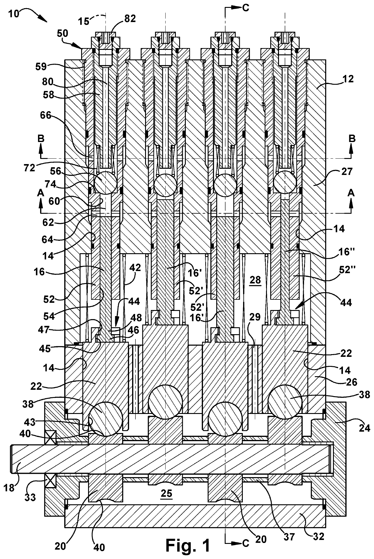
[0027]Turning to FIG. 1, a cross-sectional side view of an exemplary lubrication pump 10 is shown. The lubrication pump 10 generally includes a housing 12 defining an internal housing bore 14, a piston 16 slidably movable within the internal housing bore 14 along a longitudinal axis 15, a drive shaft 18 having an eccentric cam 20, and a connector 22 configured to engage the eccentric cam 20 and the piston 16 for imparting reciprocating driving motion to...


PUM


Abstract

A lubrication pump includes a housing defining a bore, an adjustable cylinder sleeve within the bore, and a piston slidably movable within the bore along a longitudinal axis of the bore. A connector may be drivingly interposed between a cam and the piston for driving the piston in reciprocating axial motion. The connector may have a coupling for engaging the piston, which may enable rotational engagement between the connector and the piston. The connector may have a roller for bearing engagement with the cam, which may enable the connector to rotate about the longitudinal axis relative to the housing as the connector moves axially within the bore. The cam may be laterally displaceable relative to the connector. The cylinder sleeve may be adjustable relative to the piston for varying lubricant fluid output flow. The cylinder sleeve and corresponding piston may be interchangeably disposed in the housing.

Description

RELATED APPLICATIONS[0001]This application claims the benefit of U.S. Provisional Application No. 62 / 398,934 filed Sep. 23, 2016, which is hereby incorporated herein by reference.FIELD OF INVENTION[0002]The present invention relates generally to a lubrication system, and more particularly to a lubrication pump for delivering lubricant through the lubrication system.BACKGROUND[0003]Centralized lubrication systems are widely used in industrial and heavy-duty mobile equipment applications to lubricate bearing surfaces on a machine. The centralized lubrication system uses a lubrication pump to deliver controlled amounts of lubricant, such as grease or oil, from a reservoir through one or more fluid conduits to lubricate the bearing surfaces of one or more machines. The lubrication pump typically includes a motor that drives a camshaft, which in turn drives a piston within a bore of a pump housing. As the piston moves back and forth within the housing bore, the lubricant fluid is forced ...

Claims


Application Information

Patent Timeline
Patent Type & Authority Patents(United States)
IPC IPC(8): F16N13/04F04B9/04F16J1/12F04B19/22F04B53/10F04B49/12F04B53/16F04B53/14F04B53/06
CPCF16J1/12F04B9/045F16N13/04F04B9/042F04B49/128F04B19/22F04B53/14F04B53/06F04B53/10F04B53/16F04B1/0408F04B1/0413F04B1/0426F04B1/0439F04B1/0538F04B1/07F04B49/16F04B53/04F04B53/166F16N13/14
Inventor POWELL, JOHN H.
Owner FD JOHNSON
Why Eureka
Try Eureka